
Communication System, Communication Apparatus and Method, and Computer Program

a communication system and communication apparatus technology, applied in the field of communication systems, can solve the problems of insufficient transmission rate of 480 mbps, inability to fully meet the requirements of the transmission system, so as to reduce the cost, and increase the amount of data. the effect of unit tim

Inactive Publication Date: 2009-02-26
PIONEER CORP
View PDF4 Cites 89 Cited by
  • Summary
  • Abstract
  • Description
  • Claims
  • Application Information

AI Technical Summary

Benefits of technology

The present invention provides a communication system that allows for the transmission of data through a space using a display pattern displayed on a high-speed modulating device. The system uses a first communicating apparatus with a displaying device and a second communicating apparatus with a light receiving device to receive the display pattern and obtain the data. The system can transmit a large volume of data, including video images and audio, through a space. The invention reduces the cost and complexity of the communication system by using existing equipment for the first and second communicating apparatus.

Problems solved by technology

Such a cost demerit or a demerit related to an increase in apparatus size can be a barrier particularly for the popularization of the communication system for general users.
However, in order to transmit a signal, such as video images and music, the transmission rate of 480 Mbps is not completely sufficient.
On the other hand, even in the communication method using visible light, exclusive parts, such as the LED, are necessary, and this method likely has the same problems as those of the wireless communication using the electric waves for communication.
Moreover, even in the display-use VLC, the transmission rate is extremely low, and a signal, such as video images and music, is hardly transmitted or cannot be transmitted.

Method used


Image

  • Communication System, Communication Apparatus and Method, and Computer Program
  • Communication System, Communication Apparatus and Method, and Computer Program
  • Communication System, Communication Apparatus and Method, and Computer Program

Examples


Embodiment Construction

[0073]Hereinafter, the best mode for carrying out the present invention will be explained in each embodiment in order with reference to the drawings.

(1) Basic Structure

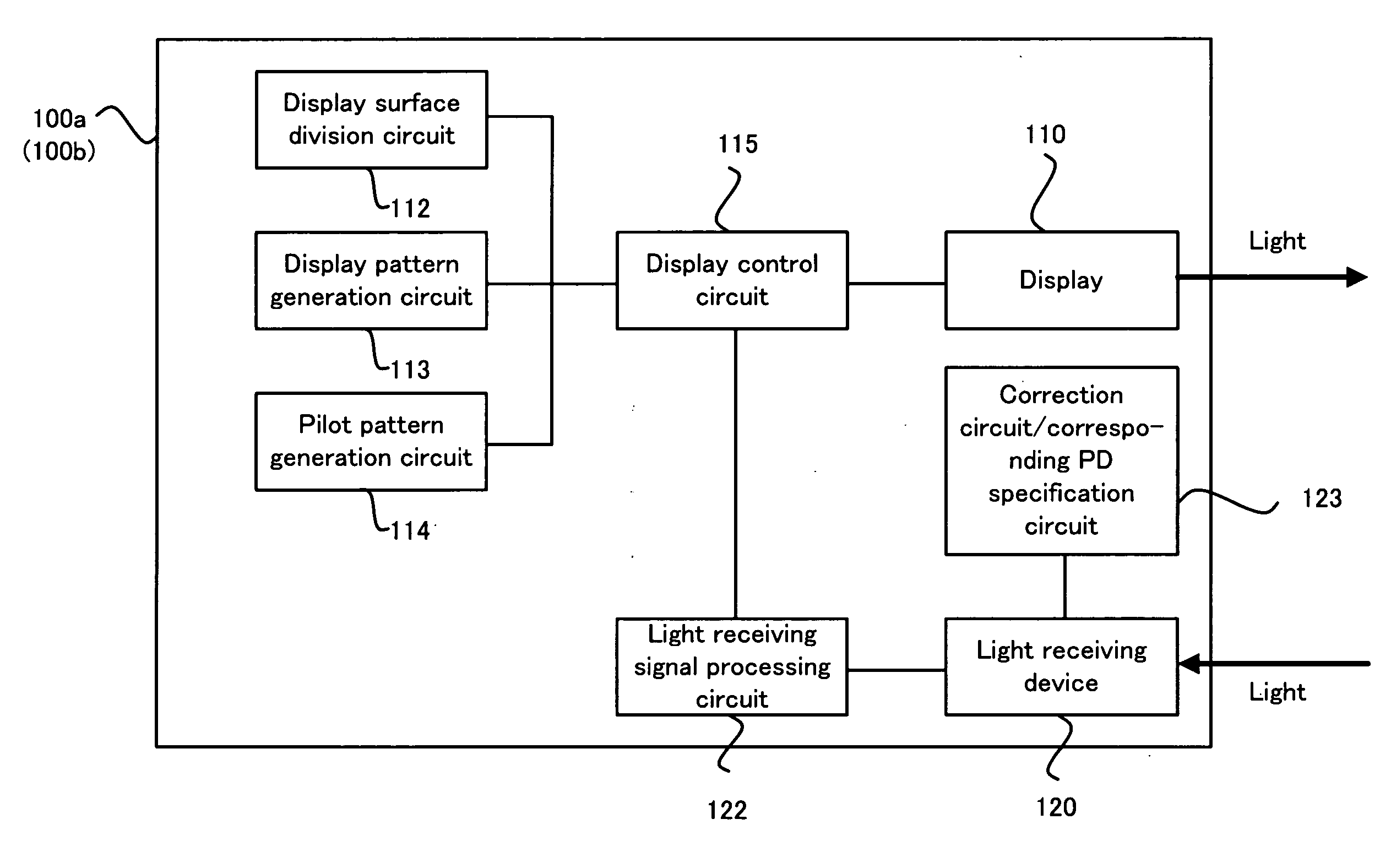
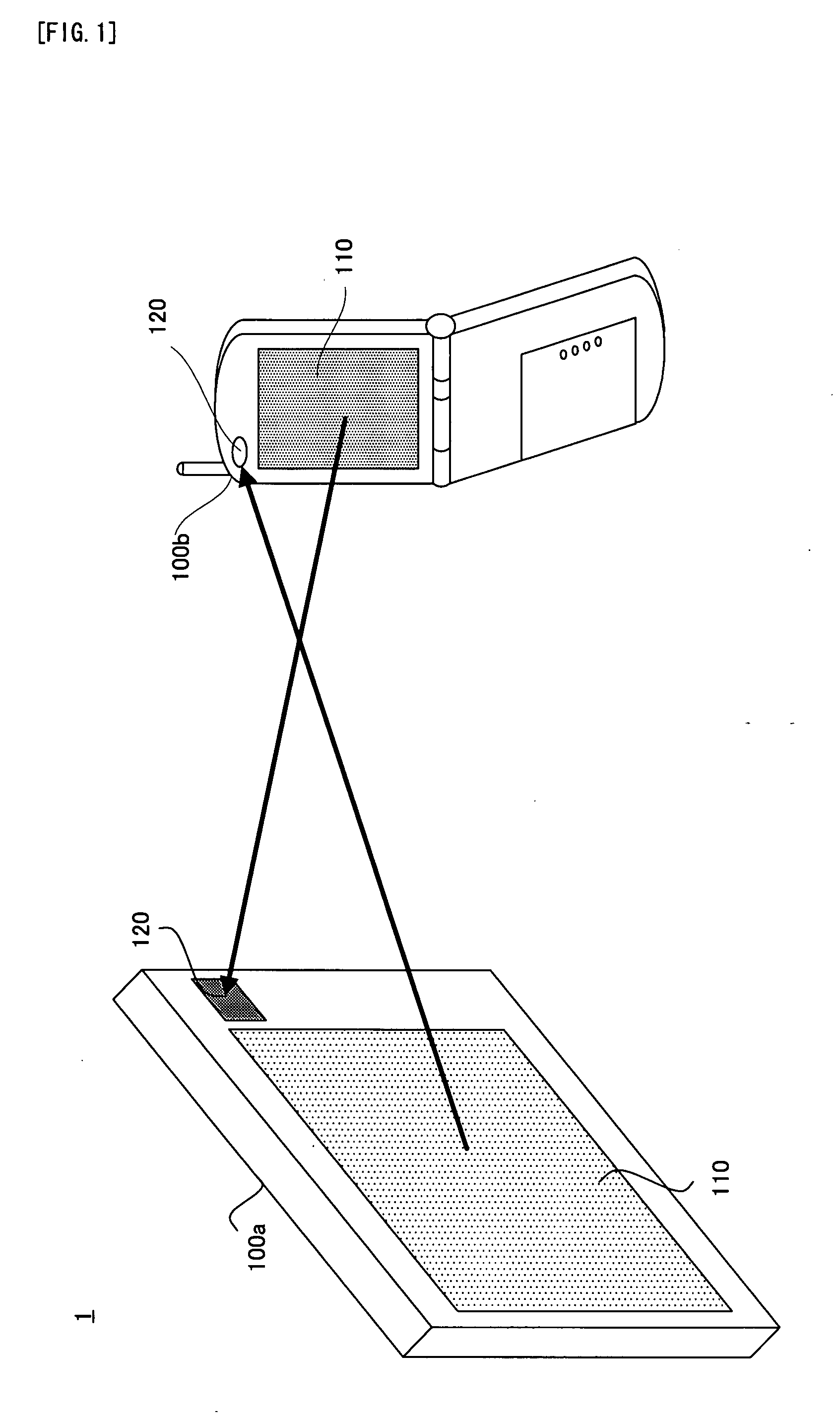
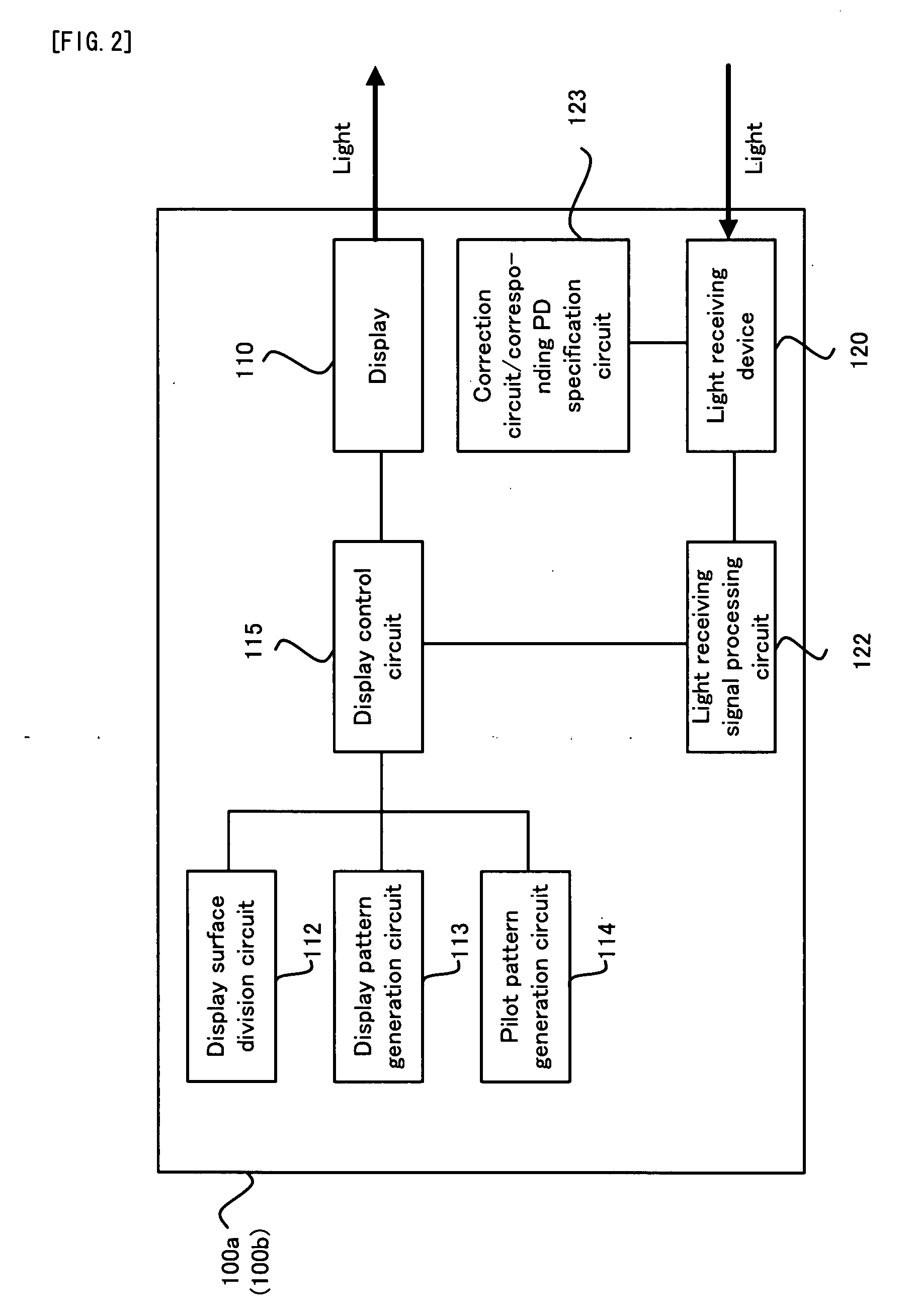
[0074]Firstly, with reference to FIG. 1 and FIG. 2, the basic structure of an embodiment of the communication system of the present invention will be explained. FIG. 1 is a schematic diagram conceptually showing the basic structure of a communication system 1 in the embodiment. FIG. 2 is a block diagram conceptually showing the basic structure of a terminal which is used for the communication system 1 in the embodiment.

[0075]As shown in FIG. 1, the communication system 1 is provided with a terminal 100a and a terminal 100b, each of which constitutes one specific example of the “communicating apparatus” of the present invention. Each of the terminal 100a and the terminal 100b is provided with: a display device 110, which constitutes one specific example of the “displaying device” of the present invention; and a light r...


PUM


Abstract

A communication system (1) is provided with: a first communication apparatus (100a); and a second communicating apparatus (100b), the first communicating apparatus is provided with: (i) a displaying device (110) which can perform high-speed modulation; (ii) a display dividing device (112) for dividing a display surface of the displaying device into a plurality of display blocks; and (iii) a controlling device (115) for controlling the displaying device to display a display pattern in each of the divided plurality of display blocks, the second communicating apparatus is provided with: (i) a light receiving device (120) for light-receiving the display pattern which is displayed on the displaying device; and (ii) an obtaining device (121) for obtaining the predetermined data on the basis of the light-received display pattern.

Description

TECHNICAL FIELD[0001]The present invention relates to a communication system, a communicating apparatus and method, in which a predetermined signal can be transmitted through a space, and a computer program which is used for the communication system or the like.BACKGROUND ART[0002]As a method of transmitting a signal through a space, wireless communication is generally known, which uses electric waves or radio waves for communication. For example, as large-scaled wireless communication, television broadcasting, satellite broadcasting, and the like are listed as one example. On the other hand, as relatively small-scaled wireless communication, wireless USB (Universal Serial Bus) communication which uses UWB (Ultra Wide Band), IRDA (Infra Read Data Association) communication, Bluetooth communication, wireless LAN (Local Area Network) communication are listed as one example.[0003]On the other hand, a method of transmitting a signal through a space without using the electric waves for c...

Claims


Application Information

Patent Timeline
Patent Type & Authority Applications(United States)
IPC IPC(8): H04B10/00H04B10/11H04B10/112
CPCH04B10/116H04B10/1143
Inventor SHINOKURA, KIICHIRO
Owner PIONEER CORP
Learn More