System and method for detecting and correcting phase error between differential signals

a technology of differential signals and phase errors, applied in the field of system and method for detecting and correcting phase errors between differential signals, can solve the problems of many limitations, cable management and convenience, and typical environment of wireless communication, and achieve the effect of improving accuracy

Inactive Publication Date: 2004-01-06
M RED INC
View PDF10 Cites 56 Cited by
  • Summary
  • Abstract
  • Description
  • Claims
  • Application Information

AI Technical Summary

Benefits of technology

It is desired to detect and reduce or otherwise eliminate phase errors between differential signals, such as the I / Q carrier signals of a quadrature oscillator. The reduction in phase error increases the amount of data that can be transmitted in accordance with the RF quadrature modulating technique.
It is appreciated that a radio transceiver may be implemented with a phase error detector in accordance with the present invention. The receiver includes I and Q radio frequency (RF) mixers that receive the I and Q carrier signals, respectively, to separate the carrier signals from the I and Q portions of the received signal. The transmitter includes similar I and Q RF mixers that mix the I and Q carrier signals, respectively, with I and Q transmit signals, respectively, to develop a combined signal for transmission. The radio transceiver includes a quadrature oscillator with phase error detection feedback in accordance with embodiments of the present invention that enables accurate I and Q carrier signals. It is noted that a single phase error detector may be employed for both transmit and receive circuits. A switched phase error detector is contemplated for half-duplex operation in which only one of the transmit and receive circuits is operational at any given time. Alternatively, separate transmit and receive phase error detectors may be provided adjacent corresponding transmit and receive mixers for improved accuracy.

Problems solved by technology

Wired networks provide a certain level of convenience but have many limitations such as various cable management and convenience issues.
The typical environment for wireless communications, however, is very noisy and not optimal for communications.
For example, most homes and workplaces include many electronic devices resulting in an electronically noisy environment that may interfere with WLAN communications, such as microwave ovens, garage door openers, radios, television sets, computer systems, etc.
For example, most environments or rooms include multiple reflective services, creating multipath noise.
Movement of items or devices or the like such as hands, bodies, jewelry, mouse pointers, etc., or activation of electronic devices, such as cooling fans or the like, affects the overall wireless communication path and potentially degrades wireless communication performance.
Because of the dynamic and unpredictable environment through which wireless communications must be made, wireless communications are generally less robust and less reliable than corresponding wired communications.
Also, A significant amount of overhead is required for successful wireless communications.
Collision detection techniques, such as commonly used in Ethernet wired environments, are not particularly useful in wireless communications since a transceiver is unable to receive a signal while transmitting.
Therefore, many rules and timing constraints must be followed for wireless devices to communicate with each other in half duplex mode.
However, imperfections in the quadrature generation and / or distribution circuits typically cause quadrature phase errors.
This has proven difficult to achieve in typical wireless transceiver configurations.
Within the transceiver circuitry, a mismatch in parasitic capacitance of 11 fempto Farads (fF) across a 100-ohm resister can generate a one-degree phase error.
A local oscillator chain of one or more buffer stages may cause accumulated timing errors between I and Q that may exceed several degrees.

Method used


Image

  • System and method for detecting and correcting phase error between differential signals
  • System and method for detecting and correcting phase error between differential signals
  • System and method for detecting and correcting phase error between differential signals

Examples


Embodiment Construction

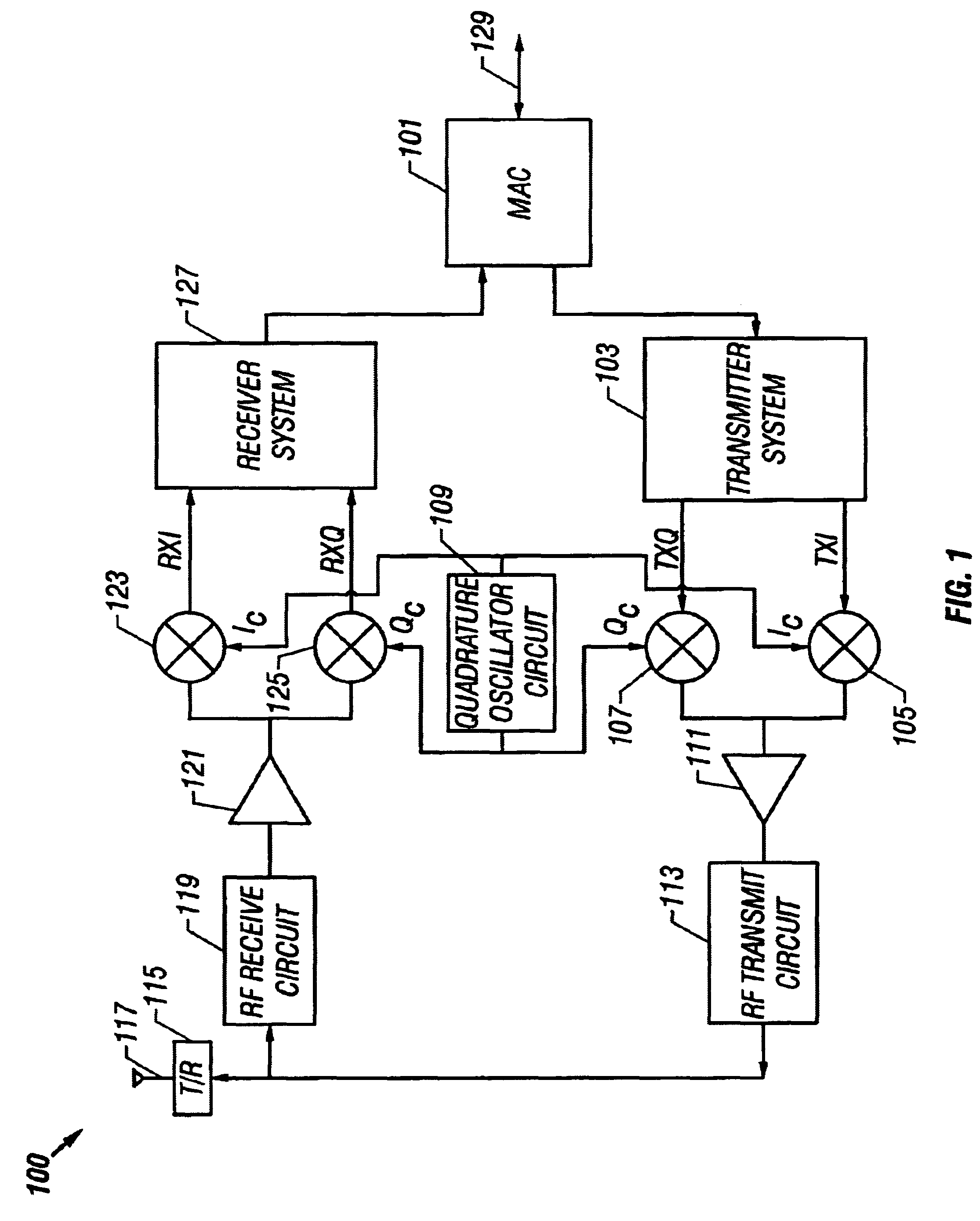
FIG. 1 is a simplified block diagram of an exemplary wireless transceiver 100 that includes one or more phase error detectors 300 (FIG. 3) implemented according to an embodiment of the present invention. The wireless transceiver 100 may utilize any desired carrier frequency and modulation technique to achieve any of the several corresponding data throughputs. For example, the wireless transceiver 100 may be configured to operate according to the Institute of Electrical and Electronics Engineers (IEEE) 802.11 with a carrier frequency of approximately 2.4 gigahertz (GHz) and with data throughputs of 1, 2, 5.5 or 11 megabits per second (Mbps). Alternatively, the wireless transceiver 100 may be configured according to IEEE 802.11 with a carrier frequency of approximately 5 GHz for achieving data throughputs of 6, 12, 24, 36 or 54 megabits per second (Mbps). The direct sequence spread spectrum (DSSS) modulation technique may be used, although many communication and modulation techniques ...


PUM


Abstract

A phase error detector that detects phase error between differential signals. A quadrature oscillator provides in-phase (I) and quadrature phase (Q) differential carrier signals and receives a phase error signal from the phase error detector. The oscillator maintains a quarter cycle phase delay between the I and Q carrier signals based on the phase error signal. The phase error detector includes a summing network and first and second bipolar transistor mixer circuits. The summing network develops four sum signals by summing respective pairs of the differential components of the I and Q carrier signals. A bias circuit biases the transistors to turn on at positive base voltages. The mixer circuits may include filter capacitors so that the transistors are responsive to positive base voltages. The mixer circuits develop polarity signals based on the sum signals, and the resulting phase error signal is the differential of the polarity signals.

Description

The present invention relates to modulation techniques, and more particularly to phase error detection and correction of phase error between differential signals, such as in-phase and quadrature phase carrier signals of a quadrature oscillator.DESCRIPTION OF RELATED ARTMany small networks are commonly connected through a set of wires. Wired networks provide a certain level of convenience but have many limitations such as various cable management and convenience issues. For various reasons, wireless LAN (WLAN) technology is becoming more popular. Radio frequency (RF) appears to be the technology of choice for establishing a viable WLAN. The typical environment for wireless communications, however, is very noisy and not optimal for communications. For example, most homes and workplaces include many electronic devices resulting in an electronically noisy environment that may interfere with WLAN communications, such as microwave ovens, garage door openers, radios, television sets, compu...

Claims


Application Information

Patent Timeline
Patent Type & Authority Patents(United States)
IPC IPC(8): H03D3/00H03L7/08H04B1/30H03L7/081H03L7/085H04L27/00H03G3/20H03G3/30H04L27/20H04L27/227H04L27/36
CPCH03D3/008H03D3/009H03L7/0812H03L7/085H04B1/30H04L27/0014H04L27/2273H04L2027/0016H04L2027/0057H04L2027/0067H04L2027/0051H04L5/16
Inventor PRENTICE, JOHN S.
Owner M RED INC
Why Eureka
Try Eureka