
Image forming apparatus with opening/closing member

a technology of opening/closing member and image forming apparatus, which is applied in the direction of electrographic process apparatus, instruments, optics, etc., can solve the problems of reducing the temperature of the cover, giving the user an unpleasant feeling when touching the cover, etc., and achieves the effect of preventing heat emission and minimizing the temperature rise of the cover

Inactive Publication Date: 2009-02-26
SAMSUNG ELECTRONICS CO LTD
View PDF4 Cites 30 Cited by
  • Summary
  • Abstract
  • Description
  • Claims
  • Application Information

AI Technical Summary

Benefits of technology

[0011]Therefore, it is an aspect of the embodiment to provide an image forming apparatus that can minimize a temperature rise of a cover by substantially preventing heat emission from a fusing device to an outside.
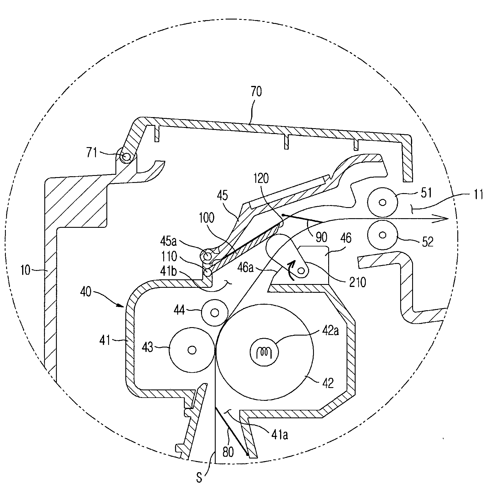
[0026]The fusing device may include a paper guide adjacent to the outlet of the fusing device, the opening / closing member may have an inclined end portion, and the inclined end portion of the opening / closing member may contact a guide surface of the paper guide to prevent heat from leaking out of the fusing device.

Problems solved by technology

Because a user frequently touches the cover whenever inspecting the interior of the apparatus, if the cover becomes hot by the heat transferred from the fusing device, it gives the user an unpleasant feeling when touching the cover.
The above heat shielding member can temporarily intercept the heat emitted from the fusing device from being transferred to the cover, but there is a limitation in maintaining a temperature of the cover low only by the heat shielding member in a circumstance in which the fusing device continuously emits heat.

Method used


Image

  • Image forming apparatus with opening/closing member
  • Image forming apparatus with opening/closing member
  • Image forming apparatus with opening/closing member

Examples


Embodiment Construction

[0036]Reference will now be made in detail to an embodiment, examples of which are illustrated in the accompanying drawings, wherein like reference numerals refer to like elements throughout. The embodiment is described below to explain the present invention by referring to the figures.

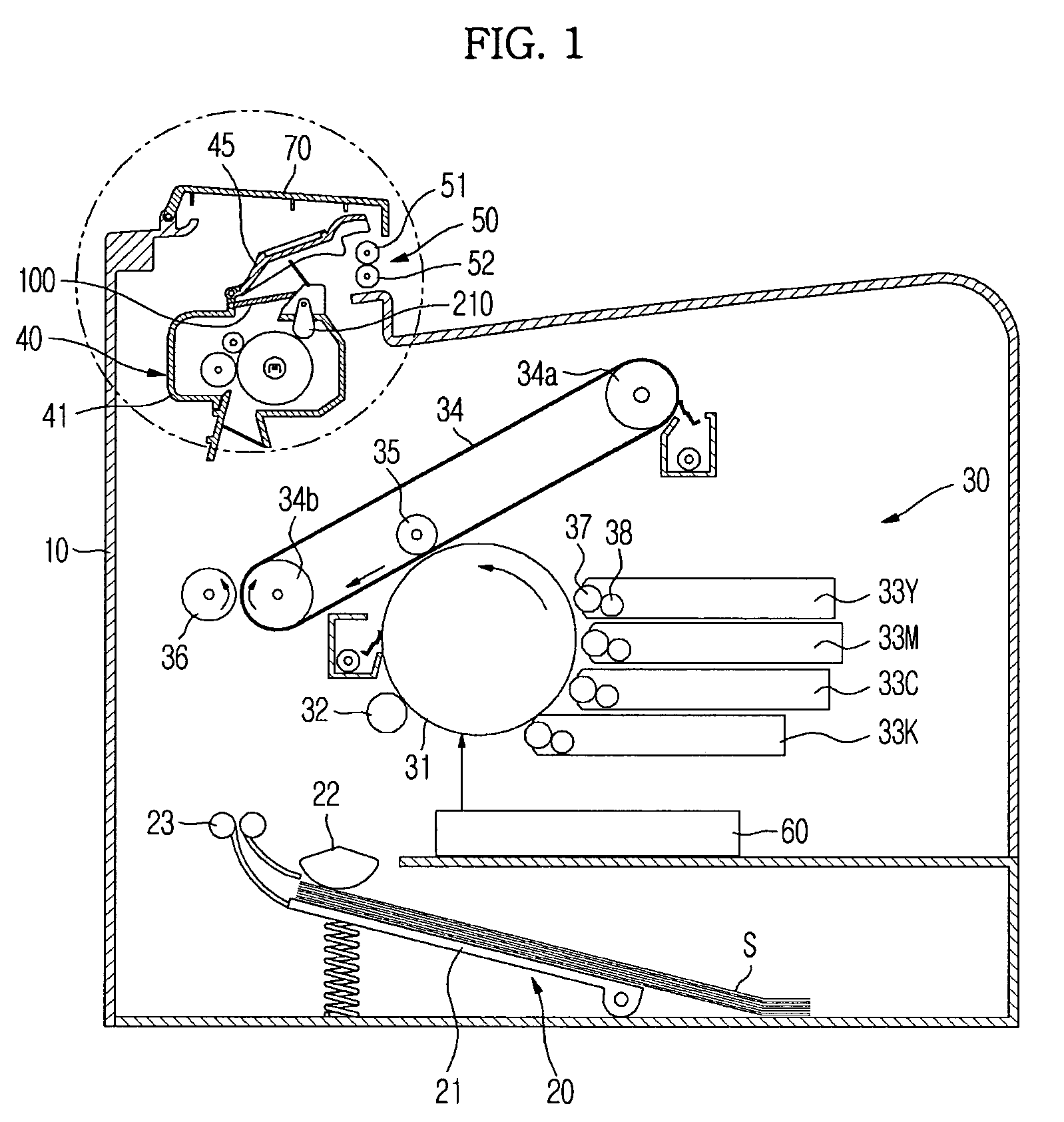
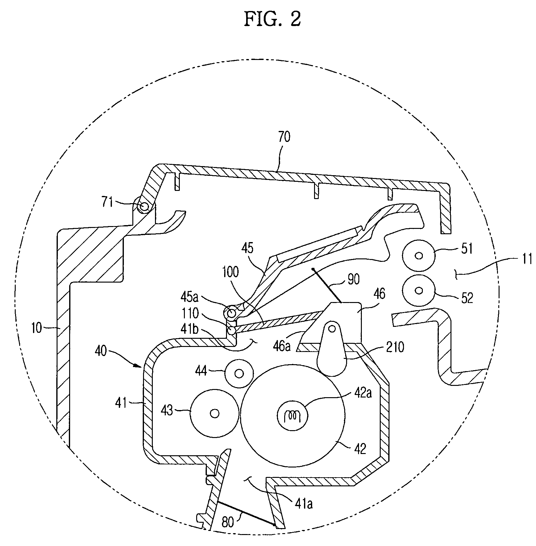
[0037]FIG. 1 is a sectional view illustrating a constitution of an image forming apparatus in accordance with the present embodiment, and FIG. 2 is an enlarged view of a portion of the image forming apparatus shown in FIG. 1. FIG. 3 is a view illustrating a state in which an opening / closing member pivots by a cam member to open an outlet of a fusing device in FIG. 2.

[0038]As shown in FIG. 1, an image forming apparatus according to the present embodiment includes a main body 10 forming an exterior appearance, a paper feeding device 20 to supply a printing medium, i.e., paper S, a developing device 30 to develop an image on the paper, a fusing device 40 to fuse an image to the paper by applying heat and...


PUM


Abstract

An image forming apparatus capable of minimizing a temperature rise of a cover by substantially preventing heat emission from a fusing device to an outside is disclosed. The image forming apparatus includes a main body, a fusing device mounted in the main body, the fusing device having an outlet to discharge paper, an opening / closing member opening and closing the outlet of the fusing device, a cam member moving the opening / closing member between a first position in which the opening / closing member closes the outlet to prevent heat in the fusing device from being emitted through the outlet and a second position in which the opening / closing member opens the outlet to permit the paper to pass through the outlet, a driving part rotating the cam member, and a control unit controlling the driving part to determine a rotational position of the cam member.

Description

CROSS-REFERENCE TO RELATED APPLICATIONS[0001]This application claims the benefit of Korean Patent Application No. 2007-0084104, filed on Aug. 21, 2007 in the Korean Intellectual Property Office, the disclosure of which is incorporated herein by reference.BACKGROUND[0002]1. Field[0003]The present invention relates to an image forming apparatus, and more particularly to an image forming apparatus that can substantially prevent heat emission from a fusing device to an outside.[0004]2. Description of the Related Art[0005]An image forming apparatus is an apparatus that prints an image on a printing medium, e.g., paper, according to an inputted image signal. As one type of image forming apparatus, an electrophotographic type image forming apparatus is configured such that light is scanned to a photosensitive body charged with a predetermined electric potential to form an electrostatic latent image on an outer peripheral surface of the photosensitive body. The electrostatic latent image is...

Claims


Application Information

Patent Timeline
Patent Type & Authority Applications(United States)
IPC IPC(8): G03G15/20
CPCG03G21/20G03G15/2064G03G15/2017G03G15/607G03G2215/00721
Inventor BAEK, SUNG KUKIM, SUNG HYUPKIM, SUN SOOHWANG, GYU DEOKKIM, JONG WOOCHO, HYUN KIRYU, JE HYOUNGKIM, TAE HEE
Owner SAMSUNG ELECTRONICS CO LTD
Learn More