Arrangement for injecting and affixing a reinforcing or anchoring element in a rock wall

a technology for reinforcing or anchoring elements and rock walls, which is applied in earth-moving drilling, mining structures, construction, etc., can solve problems such as cracks in seals, cracks in cement “plugs”, and failure to meet the requirements of appointing personnel,

Inactive Publication Date: 2009-02-26
ATLAS COPCO CRAELIUS
View PDF1 Cites 27 Cited by
  • Summary
  • Abstract
  • Description
  • Claims
  • Application Information

AI Technical Summary

Benefits of technology

[0017]According to a first embodiment, the check valve is disposed at the front end of the injection pipe. This embodiment is beneficial when the reinforcing and/or anchoring element is a solid rod and when the injection medium shall be pressed out into the hole behind the coupling means but in front of the seal.
[0018]According to a second embodiment, the arrangement is characterized in that the coupling means includes an axially extending and through-passing aperture and is designed to enable it to be coupled to a tubular element that form

Problems solved by technology

Work on and in rock walls often results in problems relating to crack formations, the danger of rock slides or rock slips and other hazards that make it necessary to reinforce the rock wall.
For example, such problems may occur in the building of tunnels or rock cavities, and may also apply to open-air rock walls in the construction of roads, highways and the like.
As the cement hardens it will shrink somewhat and because there is no other form of anchorage in the rock wall than that afforded by the adhesion of the cement to the rock face, there is often the danger that the entire cement-“plug”, including the reinforcement element, will loosen and at times even fall out of the hole.
Another problem experienced when working with and in rock walls is that moisture and water may obtain ingress through

Method used


Image

  • Arrangement for injecting and affixing a reinforcing or anchoring element in a rock wall
  • Arrangement for injecting and affixing a reinforcing or anchoring element in a rock wall
  • Arrangement for injecting and affixing a reinforcing or anchoring element in a rock wall

Examples


first embodiment

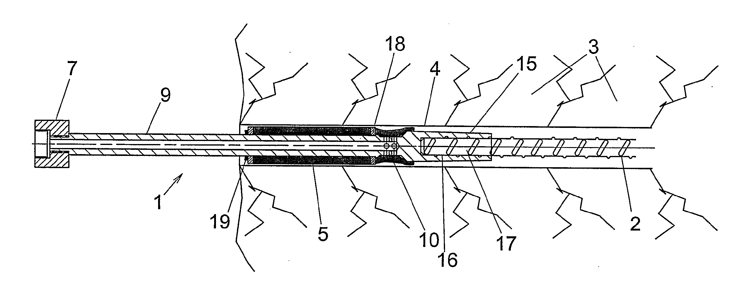
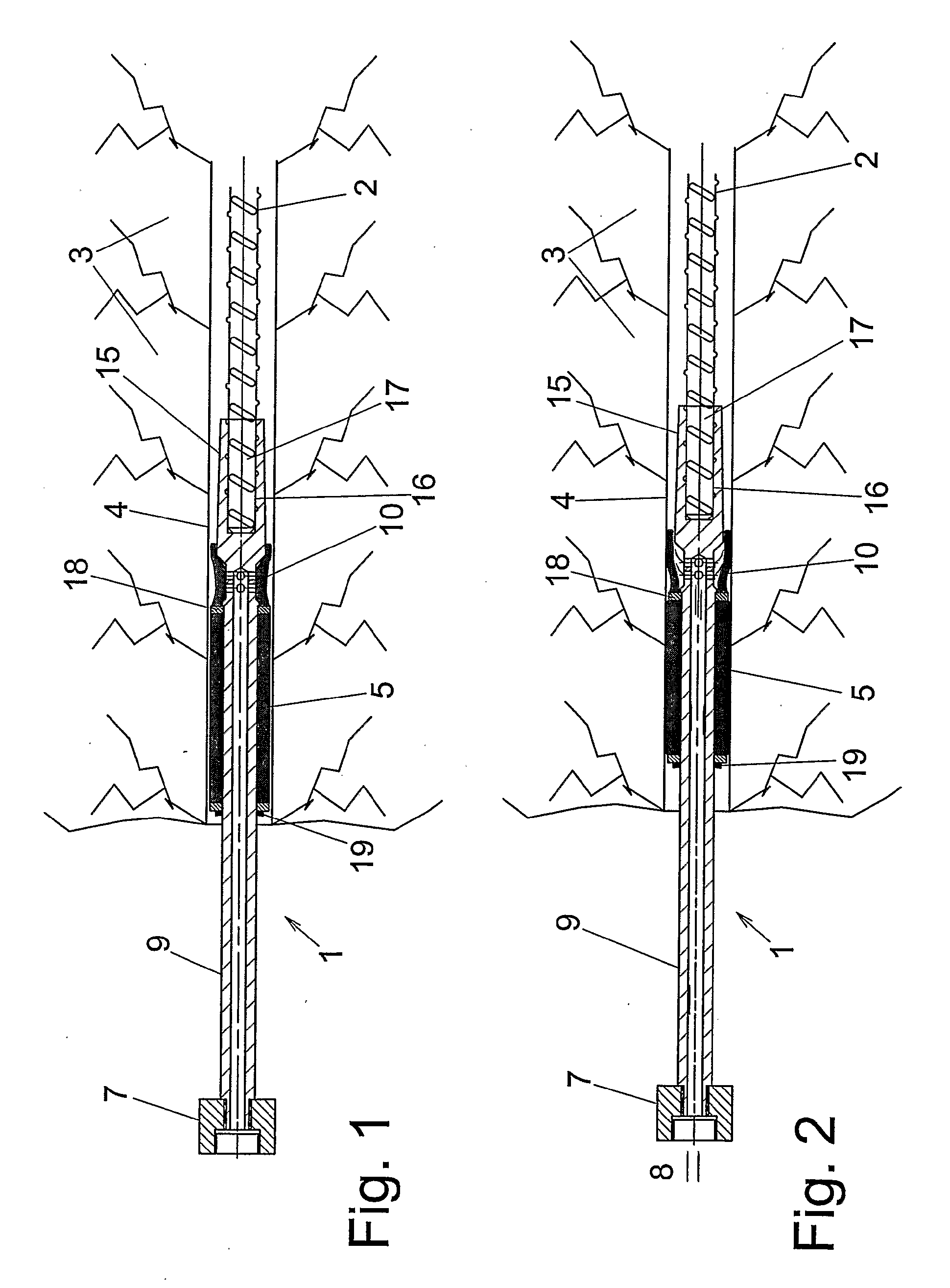
[0044]FIGS. 1 and 2 illustrate an arrangement 1 for injecting and securing a reinforcing element and / or anchoring element 2 in a rock wall 3, in accordance with the present invention. For the sake of simplicity the arrangement will be referred to solely as an injection means in the following text. Correspondingly, the reinforcing and / or anchoring element 2 will be referred to solely as the reinforcing element in the following text. This should in no way be understood as limiting the scope of the invention. The reinforcing and / or anchoring element 2 may also consist of solid iron material or a hollow tube.

[0045]FIGS. 1 and 2 show a first embodiment of the injection means 1 coupled to the reinforcing element 2, wherewith the mutually coupled members are together inserted into a hole 4 in a rock wall 3. The injection means constitutes a separate unit. The illustrated first embodiment of the injection means 1 includes a first variant of a packer-type expandable seal, namely a mechanical...

second embodiment

[0051]The inventive method will now be described with reference to FIGS. 5:1-8 and 6:1-6, these figures being related to the first and the second embodiment respectively.

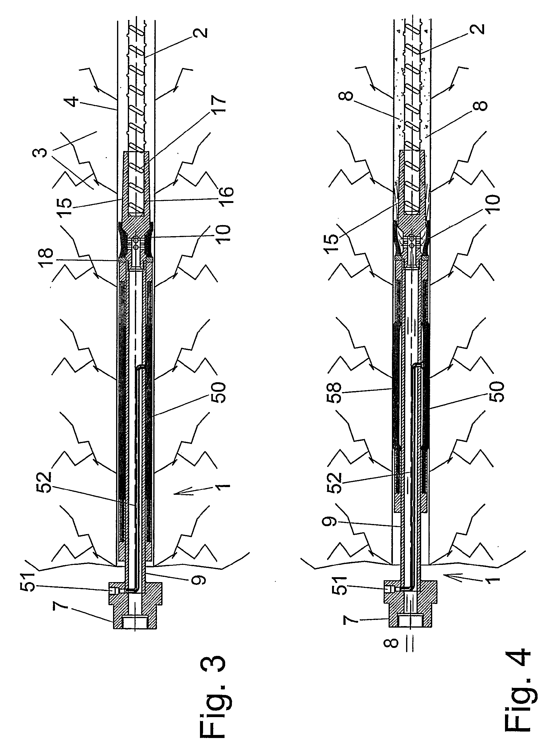
[0052]FIGS. 5:1 and 6:1 illustrate respectively a rock wall 3 in which a hole 4 has been drilled, this being the normal procedure. FIGS. 5:2 and 6:2 illustrate respectively the insertion of a reinforcing and / or anchoring element 2 into the hole 4 in the rock wall 3. The element 2 is coupled to an injection means 1 which constitutes a separate unit and includes a means 15 for coupling the injection means 1 to the reinforcing and / or anchoring element 2, connecting means 7 being intended for connection to a means for the supply of injection medium 8, an injection medium check valve 10 and an expandable seal 5 and 51 respectively.

[0053]FIG. 6:2 also shows the expansion of the seal 50 of the injection means, which in this case is achieved with the aid of a delivered hydraulically or pneumatically pressurized medium, such...

third embodiment

[0059]FIGS. 7 and 8 illustrate an injection means 1 and the attachment of a reinforcing element and / or anchoring element 62 in a rock wall 3, in accordance with the present invention. This embodiment differs from the two earlier embodiments, primarily by virtue of the fact that the coupling means 65 is also hollow, i.e. provided with a through-passing aperture or bore. In this case, the check valve 10 is located between the front end of the injection pipeline and the aperture in the coupling means 65. When also including a hollow reinforcing element 62, this enables injection medium to be fed right up to the innermost end of the reinforcing element, where the medium is then pressed out into the hole 4. It is then possible, in particular, to allow the reinforcing element 62 to comprise a drill rod that has an internal channel, i.e., in principle, a thick-walled pipe which is fitted with a drill bit 63 at its front end. This embodiment can thus be used to first drill the hole 4 in the...


PUM


Abstract

The present invention relates to an arrangement and to a method for injecting and affixing a reinforcing and/or anchoring element in a rock wall. The arrangement includes means (15; 65) for connection to a reinforcing and/or anchoring element (2; 62), an injection pipe (9) which is connected to the coupling means at a front end facing inwardly in the hole and which includes means (7) for connection to means for supplying injection medium (8). The arrangement also includes a check valve (10) for co-action with the injection medium, and an expandable seal (10; 50; 60). The arrangement is designed as a separate unit that can be loosened from the reinforcing and/or anchoring element upon completion of the injection phase. The method comprises corresponding process steps.

Description

FIELD OF THE INVENTION[0001]The present invention relates to an arrangement and a method for affixing reinforcing and / or anchoring elements in rock walls in accordance with the preamble of claim 1 and in accordance with claim 13.BACKGROUND OF THE INVENTION[0002]Work on and in rock walls often results in problems relating to crack formations, the danger of rock slides or rock slips and other hazards that make it necessary to reinforce the rock wall. For example, such problems may occur in the building of tunnels or rock cavities, and may also apply to open-air rock walls in the construction of roads, highways and the like. In such cases reinforcement is most often achieved with the aid of different methods in which reinforcement elements, normally in the form of reinforcing rods or reinforcement rounds or the like anchored in holes drilled in the rock wall. So-called rockbolts and roof bolts are examples of reinforcing and / or anchoring elements.[0003]A well known and simple method of...

Claims


Application Information

Patent Timeline
IPC IPC(8): E21D20/02E21DE21D21/00
CPCE21D21/0046E21D20/028E21D20/02E21D21/00
Inventor ERIKSSON, JANPETERSSON, STEN-AKE
Owner ATLAS COPCO CRAELIUS
Why Eureka
Try Eureka