Method of hot stamping metal parts

a metal part and hot stamping technology, applied in the direction of metal-working feeding devices, forging/pressing/hammering equipment, handling devices, etc., can solve the problems of limiting the throughput of the oven, affecting the quality of the metal parts, and requiring additional space and cos

Inactive Publication Date: 2009-03-05
MARTINREA INT INC
View PDF6 Cites 27 Cited by
  • Summary
  • Abstract
  • Description
  • Claims
  • Application Information

AI Technical Summary

Problems solved by technology

Ovens are generally an expensive element of the manufacturing facility, in terms of both capital and operating costs, and the throughput of the oven a limiting factor in the hot stamping process.
Alternatively, a manufacturer must run multiple ovens at the same time in order to heat the first and second parts in parallel, with attendant additional cost and space usage.

Method used


Image

  • Method of hot stamping metal parts
  • Method of hot stamping metal parts
  • Method of hot stamping metal parts

Examples


Embodiment Construction

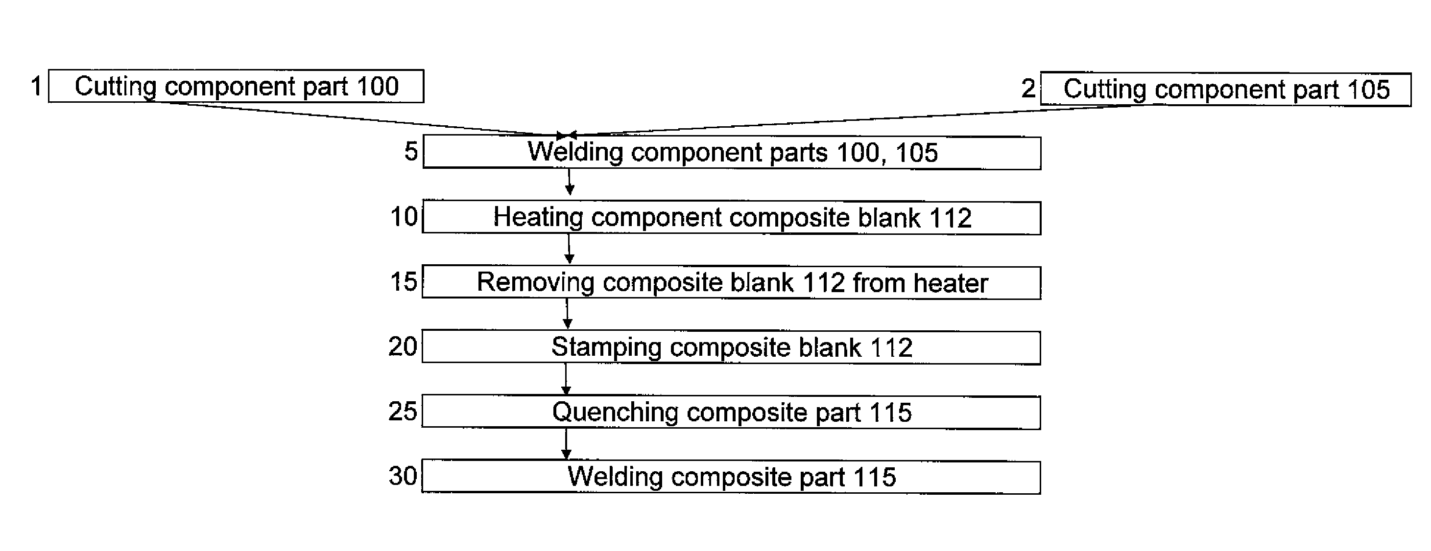
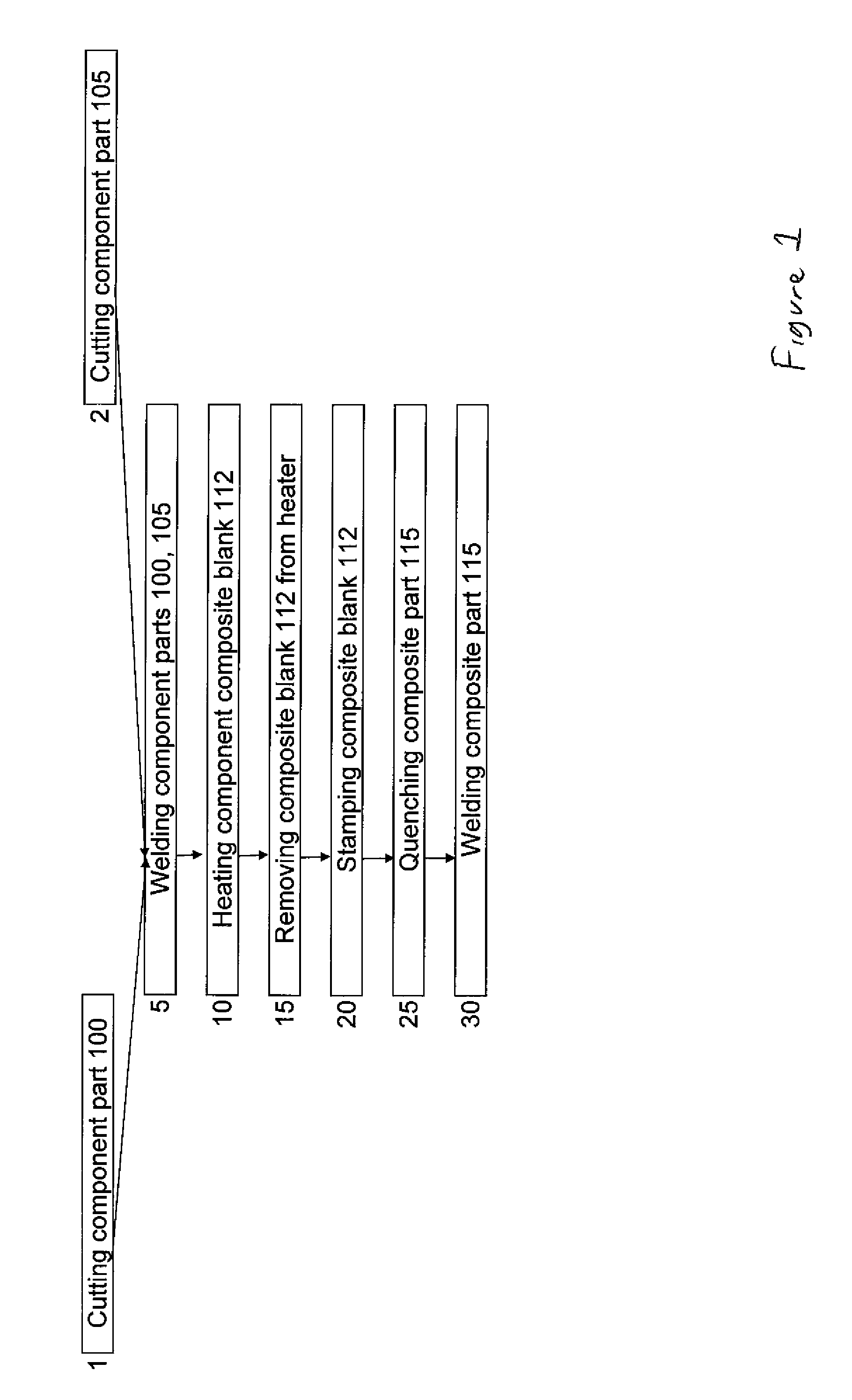
[0014]The present invention relates to a method of producing a stamped composite part, the method comprising the steps of cutting at least two metal component parts into a desired shape; welding the at least two metal component parts to each other to hold the at least two metal component parts together in a selected position as a composite blank; heating the composite blank for stamping; and stamping the composite blank to form the composite blank into a desired shape, thereby creating a stamped composite part.

[0015]The method may further comprise the step of further welding the at least two metal component parts to each other in the composite part.

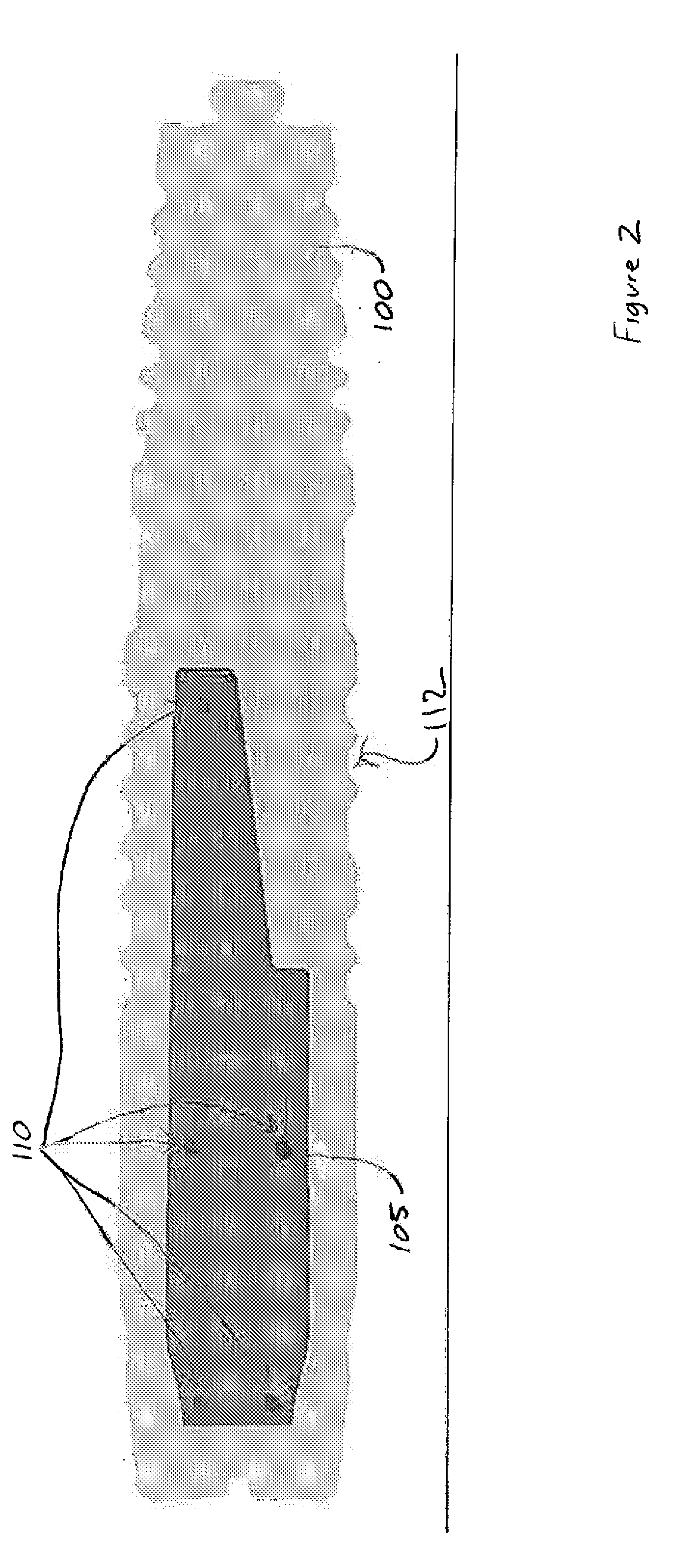
[0016]With reference to FIG. 1, the process is described in relation to creating a stamped component made from two metal component parts. The process of the invention can be used to create a stamped composite part made from more than two metal component parts. As used herein, a metal component part is a single part of metal formed from a ...


PUM

PropertyMeasurementUnit
shapeaaaaaaaaaa
temperatureaaaaaaaaaa
temperaturesaaaaaaaaaa

Abstract

A method of producing a stamped composite part, the method comprising spot welding two or more metal component parts to each other to hold the component parts in a selected position as a composite part, heating the composite part, and stamping the composite part into a desired shape. The invention also contemplates the further step of welding the two or more metal component parts to each other in the composite part.

Description

FIELD OF THE INVENTION[0001]This invention relates to the process and systems of hot stamping metal parts. In particular, this invention relates to a process of hot stamping and joining metal parts.BACKGROUND OF THE INVENTION[0002]Metal parts are often formed from sheet metal. Sheet metal is cut, bent and pressed in to the shape of the desired metal parts. After the metal part is formed, it can then be welded or otherwise attached to other metal parts created by the same process or by other means.[0003]Hot stamping is a process of forming metal parts from sheet metal stock that involves heating a portion of the sheet metal material to a high temperature for a period of time and then forming the heated material using a die.[0004]Ovens are often used to heat the pieces to the high temperatures needed. In a manufacturing facility, pieces may be continuously moved through the oven so the parts are consistently heated to the desired temperature for the desired length of time. Ovens are g...

Claims


Application Information

Patent Timeline
Patent Type & Authority Applications(United States)
IPC IPC(8): B21K27/06
CPCB21D22/02B21D22/022B23P15/00B23K2201/185B23K31/02B23K2101/185
Inventor CHANKO, ROBERT
Owner MARTINREA INT INC
Why Eureka
Try Eureka