Coated steel strips, methods of making the same, methods of using the same, stamping blanks prepared from the same, stamped products prepared from the same, and articles of manufacture which contain such a stamped product

a technology of coated steel and strips, applied in the field of coated steel, can solve the problems of affecting the quality of finished products, and affecting the quality of finished products, and achieve the effects of good forming properties, good corrosion resistance, and good cohesion

Active Publication Date: 2011-07-07
ARCELORMITTAL INVESTIGACION Y DESARROLLO SL
View PDF9 Cites 35 Cited by
  • Summary
  • Abstract
  • Description
  • Claims
  • Application Information

AI Technical Summary

Benefits of technology

[0113]Another advantage of the invention lies in the fact that the diffusion of to the iron in the coating is initiated at high temperature. One thus will have a better cohesion between coating and steel in the sheet. In another form of the invention, the thermal treatment may be performed locally, in heavily deformed zones.
[0114]According to the invention, the sheet, in the delivery state in a coil or in a sheet, the thickness of which may range between 0.25 mm and 15 mm, has good forming properties and a good resistance to corrosion as well as a good capacity for painting or gluing. Preferably, the steel sheet or blank has a thickness less than 3 mm, since the cooling rates that may be achieved after quenching are high and help to obtain martensitic structures.
[0115]The steel sheet, a coated product, has a substantial resistance to corrosion in the delivery state, during forming and thermal treatments as well as during usage of the finished part.
[0116]The presence of the coating at the time of thermal treatment of the parts makes it possible to prevent any decarburization of the base metal as well as any oxidation. That is an undeniable advantage, in particular in the case of hot forming. Furthe

Problems solved by technology

Problems however are experienced with the furnace operation: the rollers may become fouled by metallic deposits which come from the pre-coating of the blanks.
If these deposits

Method used


Image

  • Coated steel strips, methods of making the same, methods of using the same, stamping blanks prepared from the same, stamped products prepared from the same, and articles of manufacture which contain such a stamped product
  • Coated steel strips, methods of making the same, methods of using the same, stamping blanks prepared from the same, stamped products prepared from the same, and articles of manufacture which contain such a stamped product
  • Coated steel strips, methods of making the same, methods of using the same, stamping blanks prepared from the same, stamped products prepared from the same, and articles of manufacture which contain such a stamped product

Examples


example 1

[0125]In a first example of implementation, a cold rolled steel sheet, 1.9 mm thick, containing by weight: 0.23% carbon, 1.25% manganese, 0.017% phosphorus, 0.002% sulfur, 0.27% silicon, 0.062% aluminum, 0.021% copper, 0.019% nickel, 0.208% chromium, 0.005% nitrogen, 0.038% titanium, 0.004% boron, 0.003% calcium-has been pre-coated with an aluminum-based alloy with composition 9.3% silicon, 2.8% iron, the remainder being aluminum and unavoidable impurities. According to the conditions of fabrication, namely the settings of the blowing devices on the operating line, sheets of 120 m long and 650 mm wide with various thickness ranges were produced.[0126]Sheet A (according to the invention): The thickness tp1 and tp2 on each side of the sheet was controlled to be within the range (20-33) micrometers, at every location of the two faces of the sheet, both in the longitudinal (or rolling) direction and in the transversal direction. Measurement was performed continuously with thickness gage...

example 2

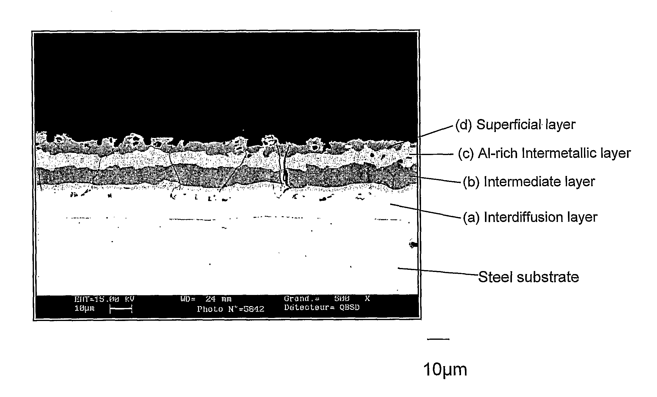
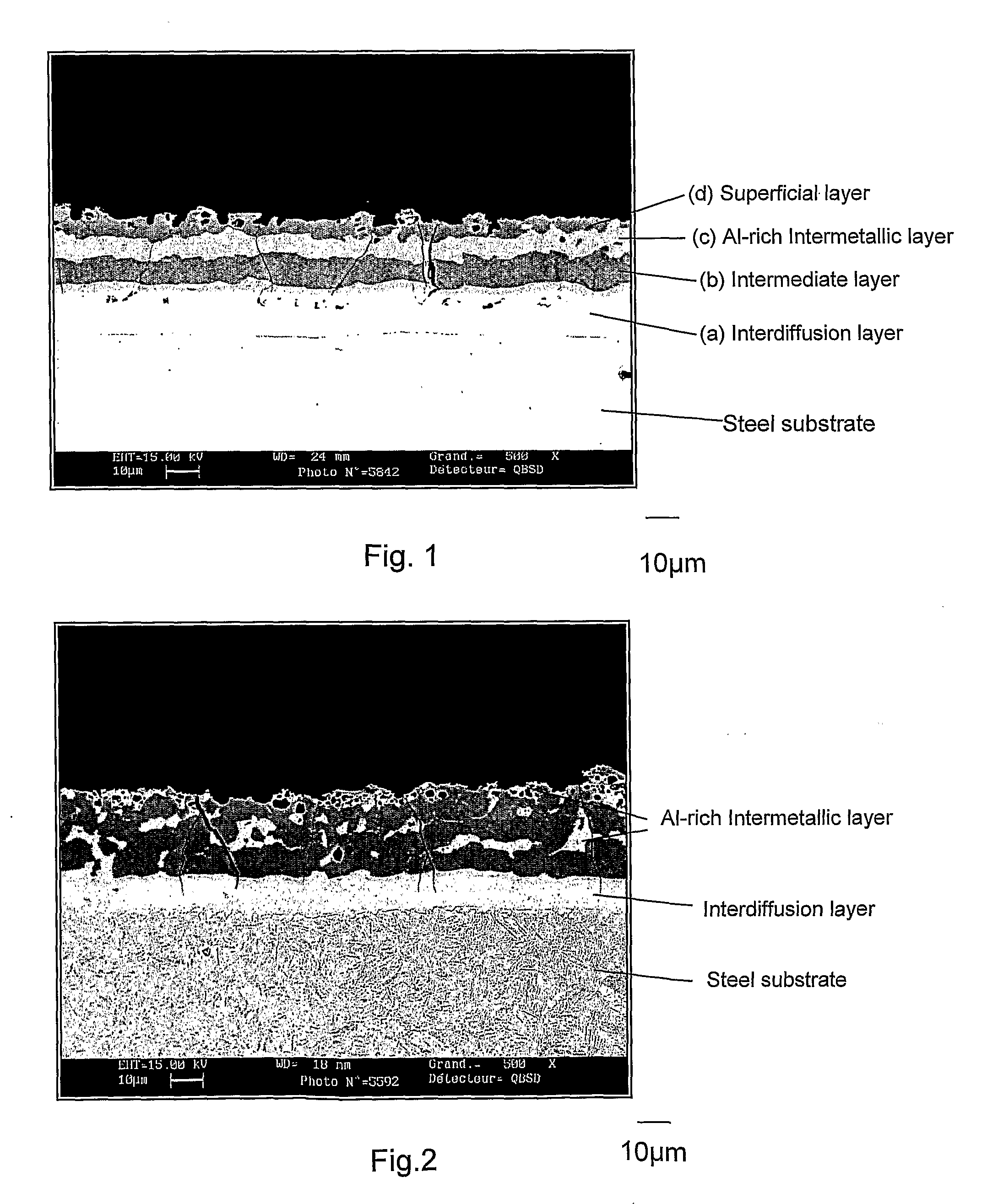
[0132]i) Conditions according to the invention: In a second example of implementation, a cold rolled steel sheet, 1,2 mm thick, 120 m long and 650 mm wide, with same composition and same pre-coating as in example 1, has been fabricated. The sheets were afterwards cut into blanks which were heated at 920° C. for 6 mn, this time including the heating phase and the holding time. Heating rate Vc between 20 and 700° C. was 10° C. / s. The blanks were finally hot stamped and quenched in order to obtain full martensitic structures.

[0133]The parts obtained after hot-stamping are covered by a coating, 40 micrometers thick, illustrated at FIG. 1, which has a four layer structure. Starting from the steel substrate, the layers are the following:[0134](a) Interdiffusion layer or intermetallic layer, 17 micrometers thick. This layer is itself composed of two sub-layers. Hardness HV50g ranges from 295 to 407, and the mean composition is: 90% Fe, 7% Al, 3% Si.[0135](b) Intermediate layer, appearing d...

example 3

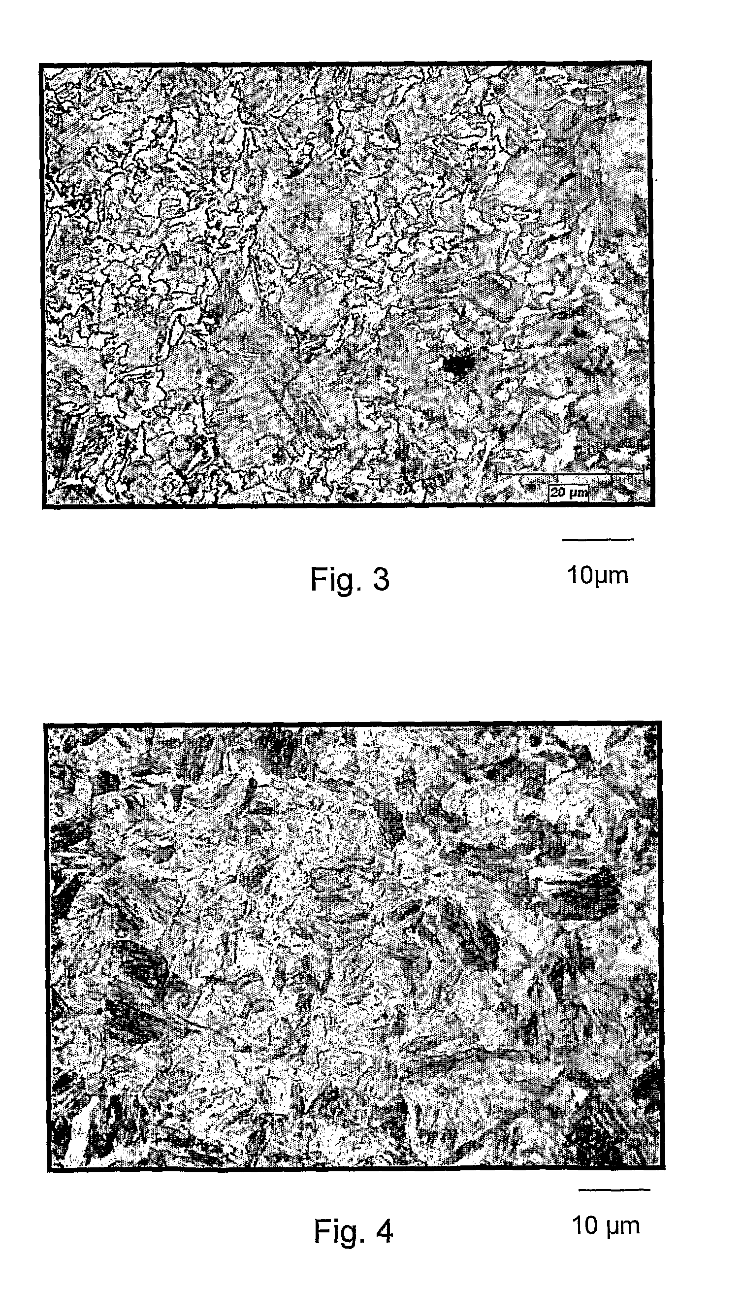
[0147]In a third example of implementation, a cold rolled steel sheet of the example 1 was cut into blanks of 500×500mm2 which were heated at 920° C., during 6 mn, then hot stamped and cooled in tools, in such conditions that two different cooling rates were obtained:[0148](A): Cooling rate: VA=30° C. / s[0149](B): Cooling rate: VB=60° C. / s

Due to the shape of he parts, different deformation levels ε were created during hot stamping. In particular, some zones largely strained display deformation levels higher than 30%.[0150]As illustrated on FIG. 3, metallographic observations reveal that when ε>10%, partial bainitic or ferritic transformation occurs on parts cooled with VA=30° C. / s, mainly on former austenitic grain boundaries. On the other hand, the parts cooled with VB=60° C. / s display fully martensitic microstructure as illustrated on FIG. 4. The latter structures display superior mechanic resistance and a great homogeneity in the case of mechanical solicitation.

[0151]Thus, even in...


PUM

PropertyMeasurementUnit
Temperatureaaaaaaaaaa
Lengthaaaaaaaaaa

Abstract

Coated steel having a well defined and uniform thickness is useful and advantageous for preparing products by hot stamping. Products prepared by hot stamping such a steel are particularly advantageous when subjected to a subsequent spot welding step.

Description

FIELD OF THE INVENTION[0001]The present invention relates to, among other things, coated steels, methods of making such coated steels, including hot dipping, methods of using such coated steels, stamping blanks prepared from coated steels, stamped products prepared from coated steels, and to various uses of the invention products such as in spot welding, etc.[0002]Additional advantages and other features of the present invention will be set forth in part in the description that follows and in part will become apparent to those having ordinary skill in the art upon examination of the following or may be learned from the practice of the present invention. The advantages of the present invention may be realized and obtained as particularly pointed out in the appended claims. As will be realized, the present invention is capable of other and different embodiments, and its several details are capable of modifications in various obvious respects, all without departing from the present inv...

Claims


Application Information

Patent Timeline
IPC IPC(8): B32B15/01B21D22/00C21D9/46
CPCB32B15/012C21D9/46C23C2/12Y10T428/12396C23C2/40Y10T428/12757Y10T428/12389C23C2/26B32B15/00C21D8/02
Inventor DRILLET, PASCALSPEHNER, DOMINIQUEKEFFERSTEIN, RONALD
Owner ARCELORMITTAL INVESTIGACION Y DESARROLLO SL
Why Eureka
Try Eureka