
System and method for interfacial rheometry

a technology of interfacial rheology and system, applied in the field of rheology, can solve the problems of significant inaccuracy in known measurement approaches that fail to account for the effects of sub-phases located within the ring, and achieve the effect of reducing the number of errors and avoiding the formation of new sub-phases

Active Publication Date: 2009-03-05
WATERS TECH CORP
View PDF6 Cites 13 Cited by
  • Summary
  • Abstract
  • Description
  • Claims
  • Application Information

AI Technical Summary

Benefits of technology

[0011]In accordance with an embodiment of the present invention, the circular ribbon is provided with an opening that interrupts the ribbon and facilitates communication between a liquid surface region disposed on the outside of the circular ribbon and contacting the outer surface of the circular ribbon, and a liquid surface disposed on the inside of the circular ribbon and contacting an inner surface of the circular ribbon.
[0013]In another embodiment of the present invention, a measurement system for measuring rheological properties of a fluid interface, comprises a cylindrical chamber having a chamber wall whose inner surface defines an outer chamber radius with respect to an axis of the cylindrical chamber, the cylindrical chamber configured to retain a sub-phase that supports the fluid interface and an inner cylinder disposed within the cylindrical chamber and concentric with an axis of the cylindrical chamber, the inner cylinder having an outer surface defining an inner cylinder radius, wherein the inner cylinder is mechanically coupled to the chamber wall to prevent relative rotational or translational movement between the inner cylinder and chamber wall. The measurement system further comprises an interface-pinning feature that is preferably located on the inner cylinder as well as the outer cylinder. In accordance with an embodiment of the present invention, the interface-pinning feature defines a first boundary between a lower and upper cylindrical portion of the inner cylinder and a second boundary between a lower and upper cylindrical portion of the chamber wall, which first and second boundaries are located at the same height. The interface-pinning feature serves to pin an interface of a liquid whose surface is at the level of the interface-pinning feature, wherein a meniscus formation on the liquid is decreased or eliminated.

Problems solved by technology

Because of this, known measurement approaches that fail to account for effects from a sub-phase located within the ring are subject to significant inaccuracies.

Method used


Image

  • System and method for interfacial rheometry
  • System and method for interfacial rheometry
  • System and method for interfacial rheometry

Examples


Embodiment Construction

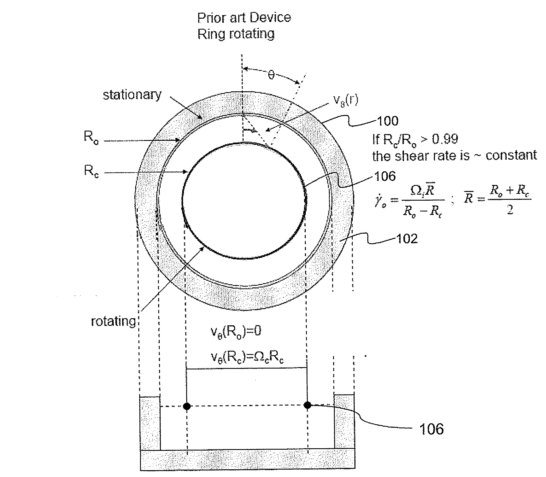
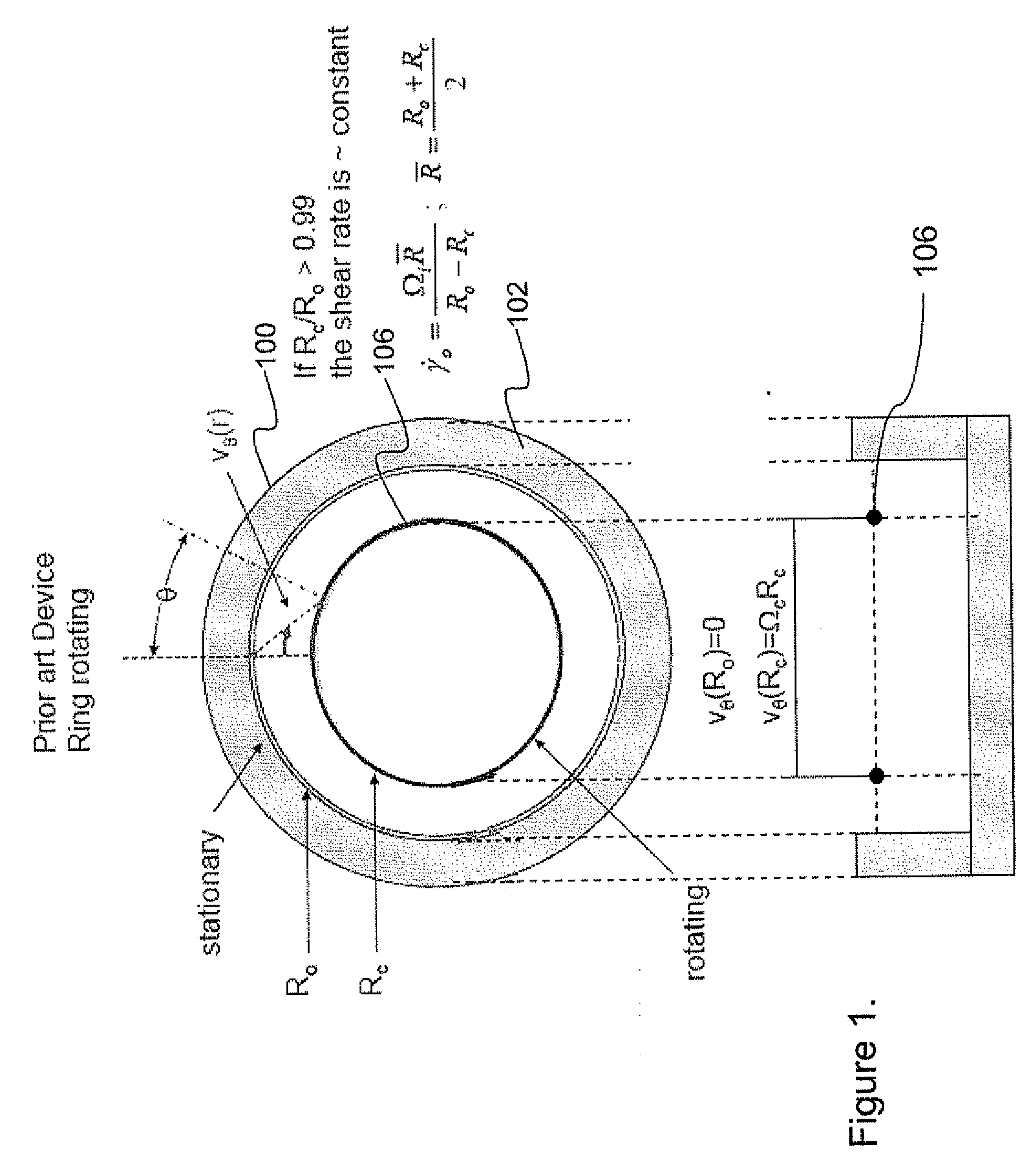
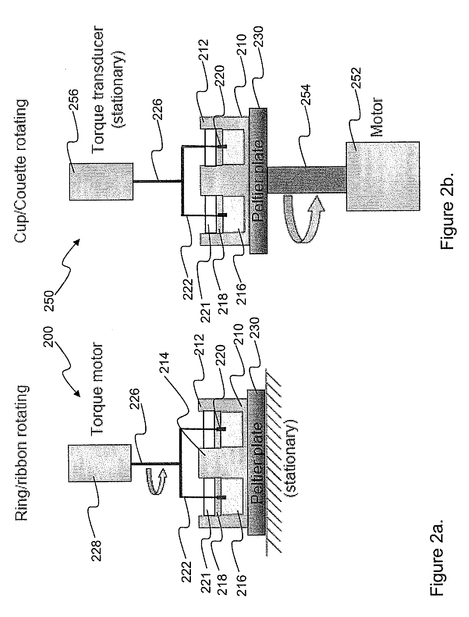
[0027]In order to clarify the present invention, a known system is depicted in FIG. 1, and embodiments of the present invention are described below with respect to FIGS. 2a-8b.

[0028]Embodiments of the present invention are related to rheometric devices that facilitate measurement of fluid interfaces. The term “fluid interface,” as used herein, generally refers to a surface region that is adjacent and contiguous to the body of a fluid. A fluid interface can be, for example, a monolayer of a material that is different from the fluid that is disposed under one surface of the fluid. Rheometric apparatus described herein operate to measure fluid interfaces at the top surface of a fluid contained within a rheometer chamber, which preferably is a cylindrical chamber. The “fluid interface” can alternatively comprise a region that is more than one monolayer thick. Unless otherwise indicated, the term “interface layer” is used herein synonymously with the term “fluid interface” to denote a t...


PUM


Abstract

An apparatus and method for performing rheological measurements of interfaces located at the top of fluid sub-phases. In one configuration, a rotating rheometer is provided with a chamber wall whose inner surface defines an outer chamber radius and an inner cylinder disposed within the cylindrical chamber and having an inner chamber radius. The rotating rheometer is configured to hold a liquid sub-phase and interface layer that can be probed using a circular ribbon that is concentric with and suspended between the inner cylinder and chamber wall. The ratio of the ribbon radius, inner chamber radius, and outer chamber radius is designed to yield an average shear rate in the inner region that is the same as an average shear rate in the outer region. In one configuration, an interface-pinning feature is provided on at least one of the inner cylinder and the chamber wall.

Description

[0001]The present invention claims priority to U.S. Provisional Patent Application No. 60 / 970,115, filed Sep. 5, 2007 and incorporated by reference herein in its entirety.BACKGROUNDField of the Invention[0002]The present invention relates generally to rheology and more specifically to systems for measuring rheological properties of thin layers and interfaces disposed on sub-phases.[0003]Measurement of the mechanical properties of interfaces and surfaces can be performed using instruments such as rheometers by specially adapting such instruments to probe the surfaces. These properties are especially of interest in characterizing food materials and cosmetics whose mechanical properties are highly dependent on the interaction at the interface between two or more phases. Typically, in known systems for measuring interfaces, a ring or a bicone is introduced into an interface layer; for example, a monolayer disposed on a fluid sub-phase contained in a cylindrical chamber. The ring can be ...

Claims


Application Information

Patent Timeline
IPC IPC(8): G01N11/14
CPCG01N11/14G01N2203/0676G01N2203/0025
Inventor FRANCK, ALOYSEVERMANT, JANFULLER, GERALD G.
Owner WATERS TECH CORP
Learn More