Method of Connecting and Fixing Ball Screw Shaft to Motor Shaft

a technology of ball screw which is applied in the direction of rod connection, mechanical equipment, gearing, etc., can solve the problems of difficult disassembly of motor shaft and ball screw sha

Inactive Publication Date: 2009-03-05
HARMONIC DRIVE SYST IND CO LTD
View PDF5 Cites 7 Cited by
  • Summary
  • Abstract
  • Description
  • Claims
  • Application Information

AI Technical Summary

Benefits of technology

[0005]An object of the present invention is to provide a method of connecting and fixing a ball screw shaft to a motor shaft so that a play-free connection state can be maintained and disassembly can be performed in a simple manner.

Problems solved by technology

However, a separate problem is encountered in this case, whereby the motor shaft and the ball screw shaft are difficult to disassemble.

Method used


Image

  • Method of Connecting and Fixing Ball Screw Shaft to Motor Shaft
  • Method of Connecting and Fixing Ball Screw Shaft to Motor Shaft

Examples


Embodiment Construction

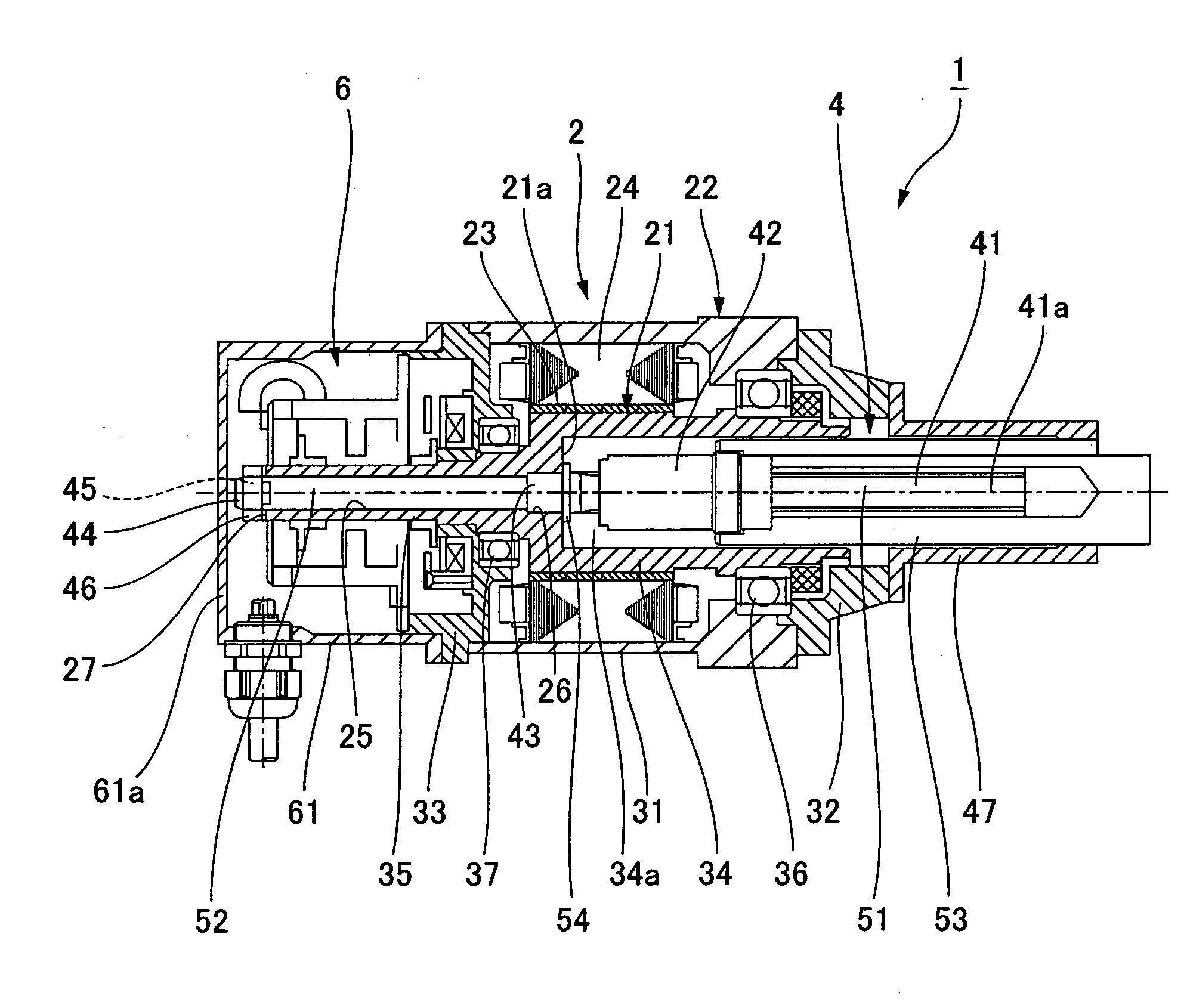
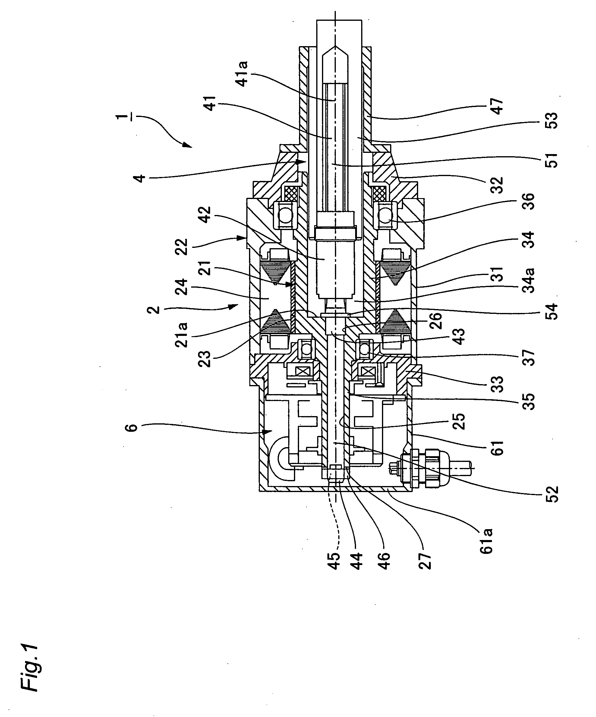
[0018]A description is provided hereunder of one example of a linear motion device to which the present invention has been applied, with reference being made to the accompanying drawings. FIG. 1 is a vertical cross-sectional schematic view showing the linear motion device of the present example. A linear motion device 1 has a motor 2, a ball screw / ball nut mechanism 4 connected to the motor 2 in a coaxial state, and a detector 6 incorporated into the rear of the motor 2. The detector 6 comprises a rotary encoder or the like and obtains the rotating position, rotating speed, and other types of rotational information about the motor 2.

[0019]The motor shaft of the motor 2 is a hollow motor shaft 21, and the shaft is supported in a rotatable state by a motor housing 22. A rotor magnet 23 is fixed to the outer periphery of the hollow motor shaft 21. A motor stator 24 is attached to the inner periphery of the motor housing 22 in a state in which the stator encloses the rotor magnet 23 acr...


PUM


Abstract

A motor (2) of a linear motion device (1) has a hollow motor shaft (21). A ball screw shaft (41) is inserted in a hollow section (25) of the hollow motor shaft (21), and a first male screw section (43), formed on the outer periphery of the ball screw shaft, is screwed into a female screw section (26), formed in the inner periphery of the hollow section, and fixed in position. A nut (46) is crewed on a second male screw section (45) formed on a shaft end section (44) of the ball screw shaft (41) that projects from the rear end of the hollow motor shaft, and the nut (46) is tightened at predetermined torque to a rear end face of the hollow motor shaft. Tensile force occurring between the first male screw section (43) and second male screw section (45) of the ball screw shaft (41) prevents loosening of the screwed section between the hollow motor shaft (21) and the ball screw shaft (41), and, as a result, the ball screw shaft (41) is kept firmly fixed to the hollow motor shaft (21) without having play. Removal of the ball screw shaft (41) from the hollow motor shaft (21) is also simple.

Description

TECHNICAL FIELD[0001]The present invention relates to a linear motion device for rotating a ball screw shaft by a motor to linearly move a ball nut, and more particularly to an improvement of a method of connecting and fixing a ball screw shaft to a motor shaft in a coaxial state.BACKGROUND ART[0002]In this type of linear motion device, a key groove or spline groove is machined in a ball screw shaft and motor shaft, and these are connected in a coaxial state. A fixing screw is used to fix a key connection section or a spline connection section between the motor shaft and the ball screw shaft.[0003]In this method, when the fixing screw loosens due to the vibration of the ball screw shaft or other such causes, the key connection section or spline connection section might develop some play in the rotation direction or axial direction.[0004]It is suggested that to prevent any play from occurring in the connection section between the motor shaft and ball screw shaft, the motor shaft and ...

Claims


Application Information

Patent Timeline
Patent Type & Authority Applications(United States)
IPC IPC(8): F16H25/20F16B7/00
CPCF16H25/20F16H25/24Y10T74/18024H02K7/06Y10T403/556F16H2025/2075
Inventor KOBAYASHI, KIYOTOYOKOYAMA, AKIHIRO
Owner HARMONIC DRIVE SYST IND CO LTD
Why Eureka
Try Eureka