Method and apparatus for in-situ testing of filtration systems

a technology for filtration systems and insitu testing, applied in auxillary pretreatment, instruments, separation processes, etc., can solve the problems of complex equipment, complex testing procedures, and inability to test in-situ, and achieve the effect of reducing the cost of equipment and equipment, saving equipment and equipment resources, and saving facilities millions of dollars

Active Publication Date: 2009-03-05
CAMFIL USA
View PDF3 Cites 20 Cited by
  • Summary
  • Abstract
  • Description
  • Claims
  • Application Information

AI Technical Summary

Benefits of technology

[0013]Embodiment described herein generally relate to a method for testing a filter disposed in a containment system. The method comprises flowing air through a filter disposed in a containment housing and changing a state of a valve assembly coupled to a downstream sample port formed through the containment housing from a first state to a second state. The first state of the valve assembly prevents flow through the downstream sample port. The second state allows f

Problems solved by technology

Numerous facilities handle hazardous and potentially fatal compounds and/or particles.
The methods described above are costly and time consuming.
The shutdown and decontamination may take

Method used


Image

  • Method and apparatus for in-situ testing of filtration systems
  • Method and apparatus for in-situ testing of filtration systems
  • Method and apparatus for in-situ testing of filtration systems

Examples


Embodiment Construction

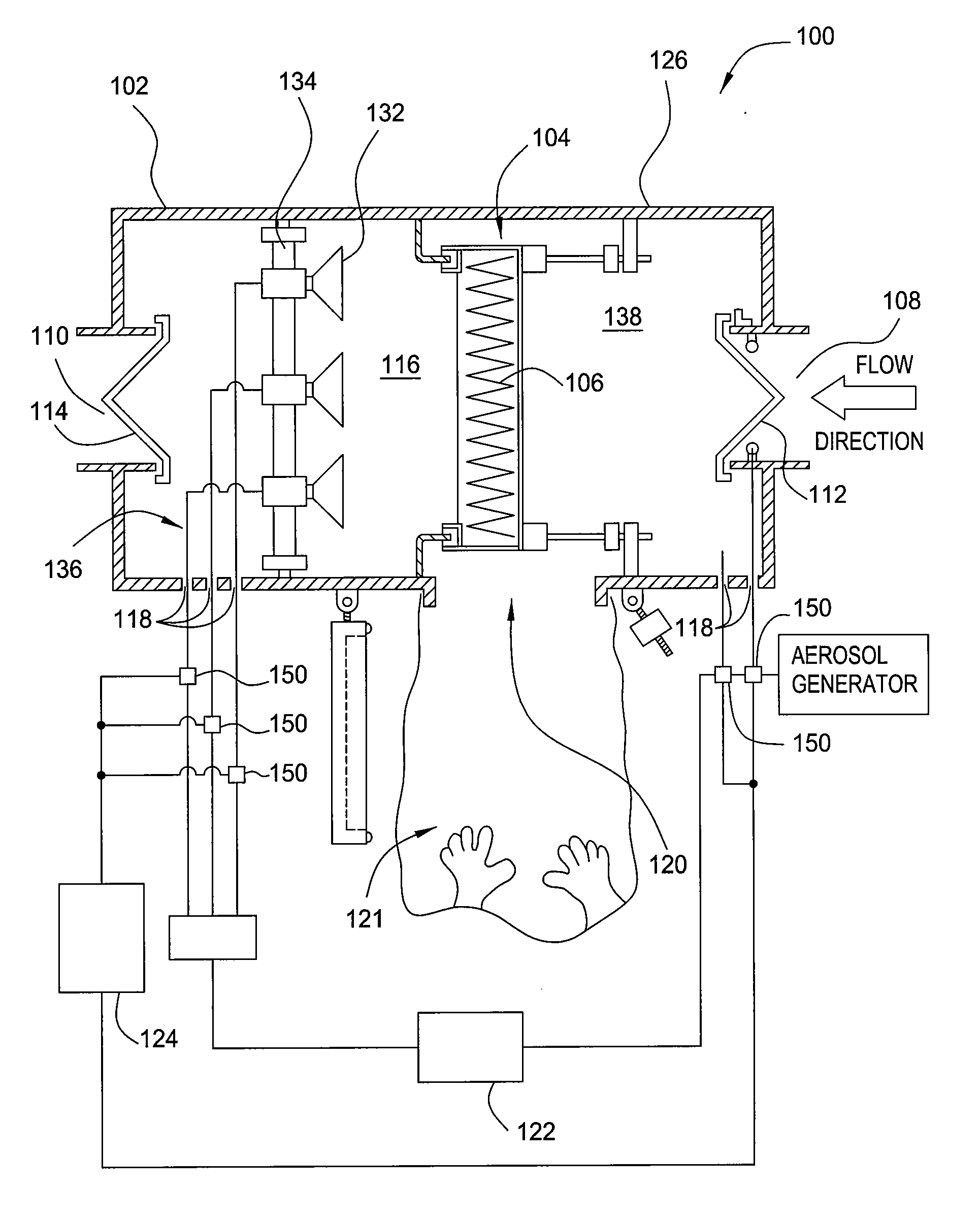
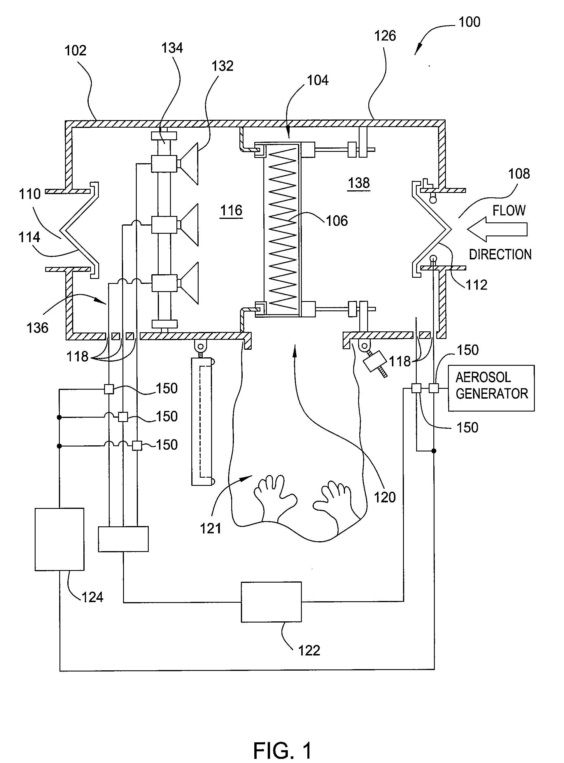
[0021]FIG. 1 is a sectional schematic view of a containment system 100. The containment system 100 ensures that air exiting or being recycled in a facility is substantially free of hazardous particles. The containment system 100 generally includes a housing 102 having one or more filters 106 disposed therein. One housing that may be adapted to benefit from the invention is described in U.S. Patent Publication No. 2007 / 0044438, filed Apr. 28, 2006, which is incorporated by reference. Another housing that may be adapted to benefit from the invention is a CAMCONTAIN™ Containment System, available from Camfil Farr, Inc., located in Washington, N.C. It is contemplated that other containment housings, including those available from other manufacturers, may be adapted to benefit from the invention.

[0022]In one embodiment, the housing 102 includes a filter mounting portion 104 for sealingly mounting the filter 106 to the housing, an airflow inlet aperture 108 and an airflow exit aperture 11...


PUM

PropertyMeasurementUnit
Flow rateaaaaaaaaaa
Concentrationaaaaaaaaaa

Abstract

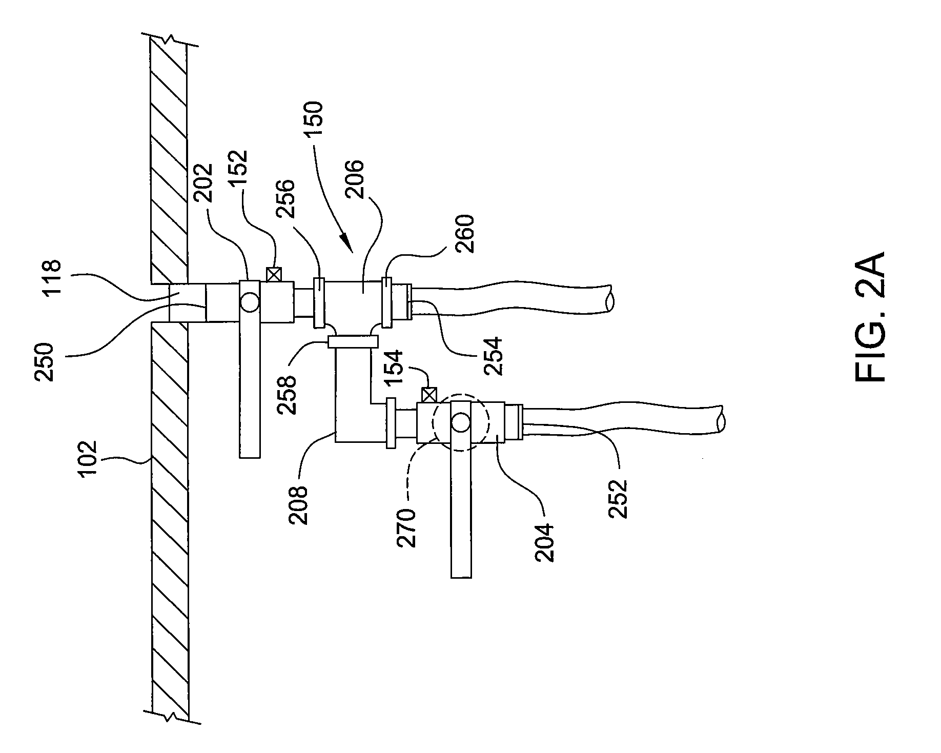
Embodiments of the invention generally provide an apparatus and method for certifying a filter in a containment system without decontaminating the containment system prior to certification. The apparatus generally comprises a valve assembly selectable between at least three operational states. A first state prevents flow from prevents flow through a port of a housing. A second state fluidly couples the port to test equipment necessary to test a filter disposed within the housing. A third state seals the port but fluidly couples the test equipment to a decontamination system.

Description

CROSS-REFERENCE TO RELATED APPLICATIONS[0001]This application claims benefit to U.S. Provisional Patent Application Ser. No. 60 / 947,198, filed on Jun. 29, 2007.BACKGROUND OF THE INVENTION[0002]1. Field of the Invention[0003]The embodiments described herein generally relate to an apparatus and method for certifying a filter in a containment system without decontaminating the containment system prior to certification. More particularly, embodiments described herein relate to a containment housing isolatable from a sample system and a decontamination system thereby allowing for in-situ testing of a filter disposed in the housing.[0004]2. Description of the Related Art[0005]Numerous facilities handle hazardous and potentially fatal compounds and / or particles. These facilities include, for example, biological safety labs, pharmaceutical manufacturing facilities, biotechnology research labs, and production facilities. The hazardous particulates may include anything that is harmful or fata...

Claims


Application Information

Patent Timeline
IPC IPC(8): B01D46/42G01N1/22
CPCB01D46/0028B01D46/008B01D46/0091G01N2001/2223B01D46/4272B01D2273/18B01D46/42B01D46/88
Inventor HUZA, MARKMORSE, THOMAS C.
Owner CAMFIL USA
Why Eureka
Try Eureka