Lubricating device

a lubricating device and valve technology, applied in the direction of valve drives, auxilaries, machines/engines, etc., can solve the problems of wasteful lubricating oil ejection, lubricating device may not be properly applied to the valve driving mechanism of a multi-cylinder engine, and the difficulty of guiding lubricating oil, so as to achieve the effect of decreasing the amount of lubricating oil

Inactive Publication Date: 2009-03-05
MAZDA MOTOR CORP
View PDF3 Cites 7 Cited by
  • Summary
  • Abstract
  • Description
  • Claims
  • Application Information

AI Technical Summary

Benefits of technology

[0005]Accordingly, an object of the present invention is to provide a lubricating device which can ensure a proper lubricating of the peripheral surface of the cam portion, decreasing the amount of the lubricating oil.
[0007]According to the lubricating device of the present invention, the above-described one of the cam portions has the above-described nozzle to supply the lubricating oil, and the other one does not such nozzle. Thereby, the number of nozzles can be reduced, so that the amount of the lubricating oil can be reduced. Meanwhile, the supply of the lubricating oil to the other cam portion described above can be achieved by the lubricating-oil guidance of the recess portion. Thereby, the lubricating between the peripheral surface of the other cam portion and the slide member can be ensured as well.
[0008]According to an embodiment of the present invention, the recess portion is configured such that the width thereof becomes narrower toward the other of the cam portions. Thereby, the amount of the collection of the lubricating oil ejected out of the nozzle can be properly increased, and the collected lubricating oil can be guided properly to the other cam portion.
[0009]According to another embodiment of the present invention, at a bottom face of the recess portion are provided a plurality of projections which extend toward the other of the cam portions. Thereby, the lubricating oil collected by the recess portion can be guided further properly to the other cam portion.
[0010]According to another embodiment of the present invention, the wall body is a cylinder head cover, or the wall body is a baffle plate which forms an oil-separating chamber inside a cylinder head cover. Thereby, the wall body can be used as parts which perfumes plural functions, so that the number of parts can be properly reduced.
[0011]According to another embodiment of the present invention, the cam portions which are disposed side by side are cam portions for two intake or exhaust valves which are provided each cylinder. Thereby, the length of the recess portion can be made properly short, so that the guidance of the lubricating oil to the other cam portion can be achieved surely.

Problems solved by technology

It may be difficult to guide the lubricating oil to a specified portion which is located away from the chain according to the above-described lubricating device.
Thus, this lubricating device may not be properly applied to a valve driving mechanism for a multi-cylinder engine.
Thus, the amount of such wasteful lubricating oil ejected would increase.
The increase of the amount of lubricating oil may increase the burden of a pump to supply the lubricating oil.
Since the pump is generally driven by the engine, such increase of the amount of lubricating oil may cause the increase of the burden of the engine.
As a result, the fuel economy of the engine would deteriorate.

Method used


Image

  • Lubricating device
  • Lubricating device
  • Lubricating device

Examples


Embodiment Construction

[0020]Hereinafter, a lubricating device according to preferred embodiments of the present invention, which is applied to a 4-cylinder inline diesel engine equipped with two intake valves and two exhaust valves for each cylinder and a DOHC type of valve-driving mechanism, will be described.

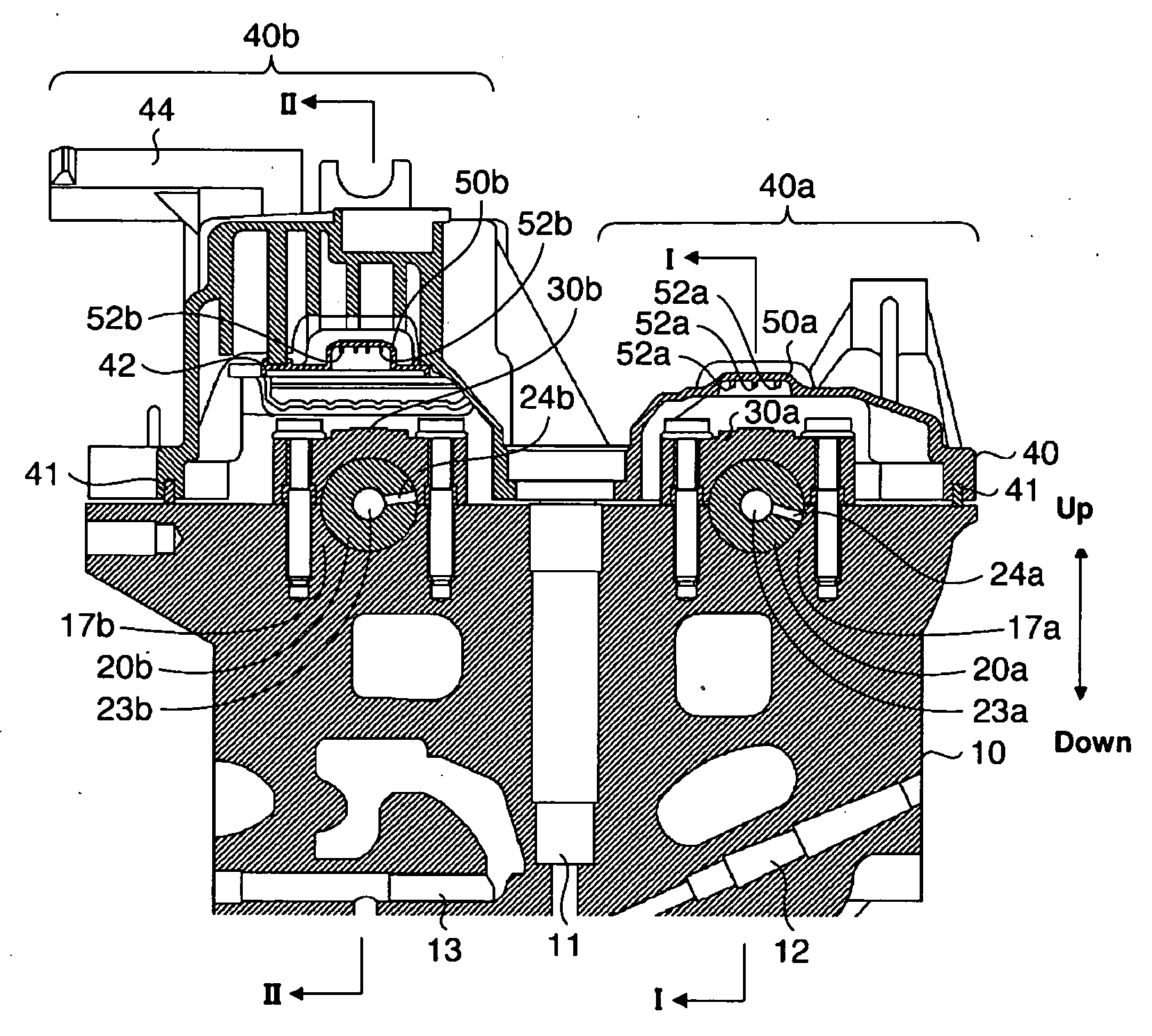
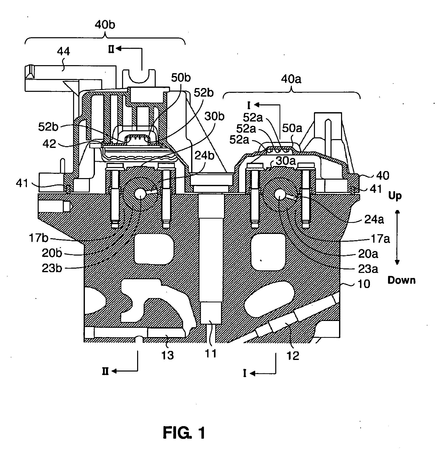
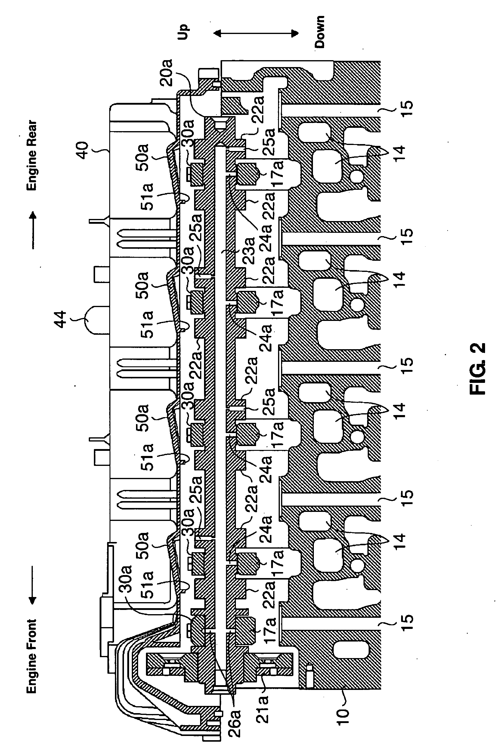
[0021]FIG. 1 is a sectional view, which is taken along a face perpendicular to a cylinder line, of a cylinder head 10 and its surroundings of the diesel engine equipped with the lubricating device according to an embodiment of the present invention. FIG. 2 is a sectional view taken along line I-I of FIG. 1. FIG. 3 is a sectional view taken along line II-II of FIG. 1. Illustration of other structures of the valve-driving mechanism than cam shafts 20 is omitted in these figures.

[0022]As shown in FIG. 1, the cylinder head 10 has an accommodation space 11 for a fuel injector (not illustrated), another accommodation space 12 for a glow plug (not illustrated), and a water jacket 13, which are formed ther...


PUM


Abstract

A lubricating device comprises a cam shaft, plural cam portions for each valve provided at the cylinder head, a valve driving mechanism to change a rotational movement of the cam portion to an opening-and-closing movement of the valve via a slide member on which a peripheral surface of the cam portion slides, an oil passage of the cam shaft, a nozzle provided at either one of the cam portions to open at the peripheral surface of the cam portion and connect to the oil passage of the cam shaft, and a wall body having a recess portion. The recess portion collects lubricating oil ejected out of the nozzle and guides the lubricating oil collected to the peripheral surface of the other cam portion when the one cam portion is located in a position in which the nozzle is not directed to the slide member.

Description

BACKGROUND OF THE INVENTION[0001]The present invention relates to a lubricating device for a valve driving mechanism of an engine.[0002]Lubricating slide portions located between a cam shaft and a journal bearing or between a cam portion and a rocker arm or a valve lifter may be required for a valve driving mechanism. Japanese Patent Laid-Open Publication No. 2001-329823, for example, discloses a lubricating device for the driving mechanism, in which at an inner-wall ceiling face of a cylinder head cover (rocker cover) is provided an oil guide portion which collects lubricating oil spread by a chain transmitting an output of a crank shat of a single-cylinder engine to a cam shaft and guides the collected lubricating oil to the valve driving mechanism. It may be difficult to guide the lubricating oil to a specified portion which is located away from the chain according to the above-described lubricating device. Thus, this lubricating device may not be properly applied to a valve driv...

Claims


Application Information

Patent Timeline
Patent Type & Authority Applications(United States)
IPC IPC(8): F01M1/06
CPCF01M1/06F01M2001/064F01M9/101F01M1/08
Inventor NAITO, MASAHIROOKADA, SHIGEMIYAMANE, JUN
Owner MAZDA MOTOR CORP
Why Eureka
Try Eureka