Nozzle system and method

a nozzle and nozzle technology, applied in the direction of cleaning with liquids, burners, combustion types, etc., can solve the problems of limited use of flexible nozzles, and significant contact between flexible nozzles and guides

Active Publication Date: 2009-03-05
ECP INC
View PDF12 Cites 44 Cited by
  • Summary
  • Abstract
  • Description
  • Claims
  • Application Information

AI Technical Summary

Problems solved by technology

Such flexible nozzles, however, may have certain limitations.
For example, since a significant pressure at the ejection of pressurized air is needed to stably turn the flexible nozzle, the flexible nozzle may be conducive for use in high-pressure applications, but not conducive for use in low-pressure applications, such as a blower for producing a delicate blow of pressurized air.
Further, the use of a horn-like guide to constrain the flexible nozzle to produce the turning action at a desired diameter may create a significant amount of contact between the flexible nozzle and the guide.
The contact may result in contamination and wearing of each of the components.
The resistance to movement due to the wear between the nozzle and the inner side of the guide may increase and reduce the ability of the nozzle to rotate.
Further, a flexible nozzle, such as that made of a synthetic resin material, may be susceptible to certain environmental conditions.
For example, the flexible nozzle may harden during the winter or in a cold climate, thereby reducing the ability of the nozzle to rotate and lessening the ability to provide the desired dispersion of the pressurized air in a turning movement.

Method used


Image

  • Nozzle system and method
  • Nozzle system and method
  • Nozzle system and method

Examples


first embodiment

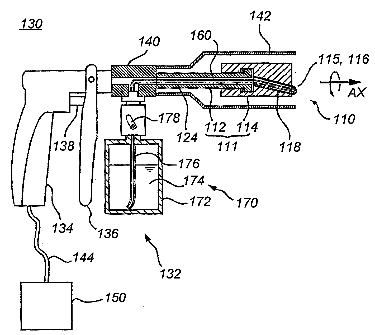
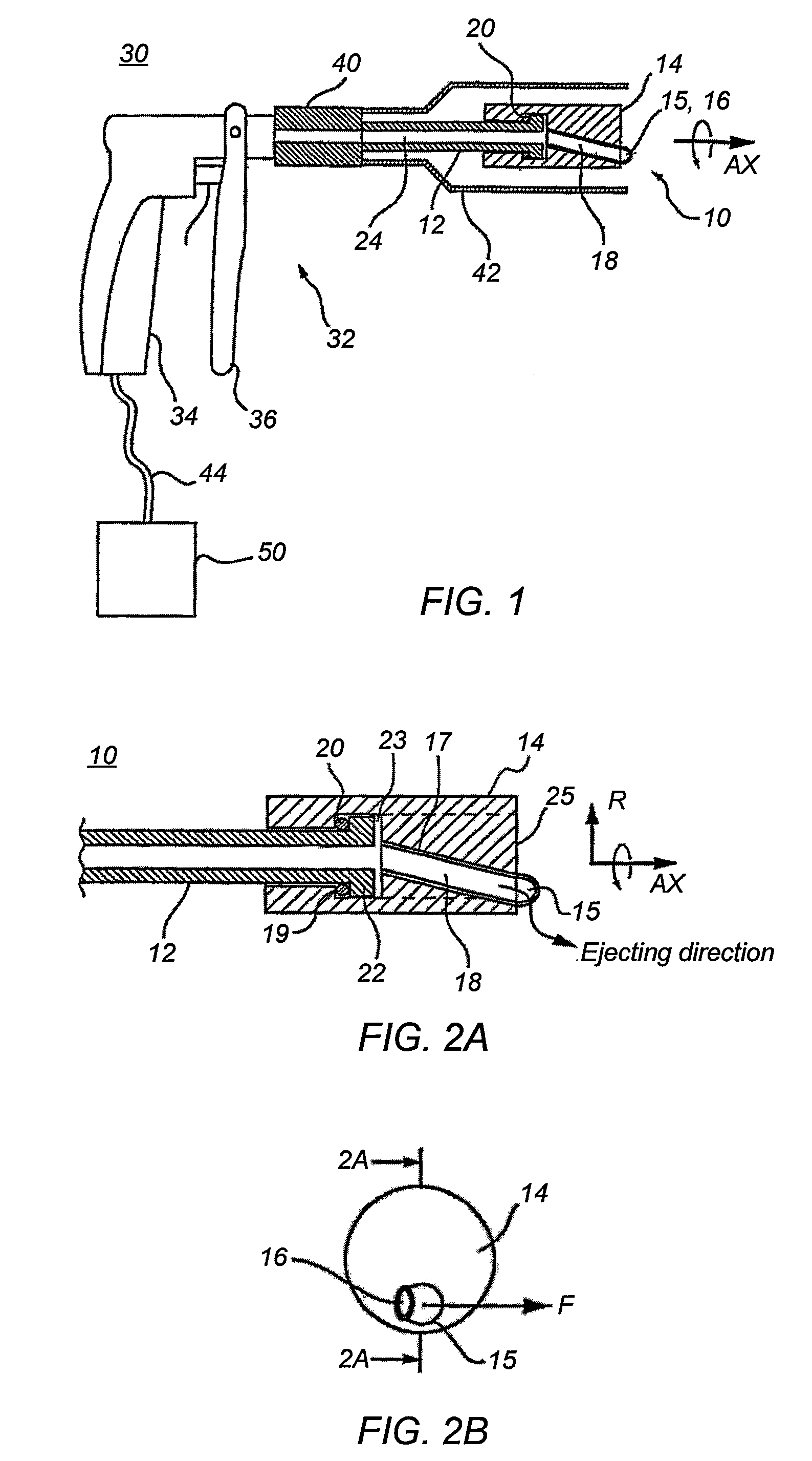
[0051]Turning now to the figures, FIG. 1 is a partially longitudinally cross sectional, schematic (side) view of a spray (air blow) nozzle 10 and a spray (air blow) apparatus 30 equipped at the distal end (at the right in the drawing) with the spray nozzle 10, showing the present invention. The arrangement of the spray nozzle 10, a joint 40, and a cover 42 is illustrated in the longitudinally cross sectional view taken along the vertical line through along the axis of rotation (AX).

[0052]FIG. 2(a) is a partially longitudinally cross sectional schematic (side) view of the spray nozzle 10 of the present embodiment. The cross sectional view of FIG. 2(a) corresponds to a view taken along the line 2A-2A of the FIG. 2(b). The proximal end (at the left in the drawing) of a fixed (stationary) tube 12 is not shown. FIG. 2(b) is a front view of the spray nozzle 10.

[0053]The spray apparatus 30 of the present embodiment is provided in the form of a spray apparatus (e.g., a dust blower) for ejec...

second embodiment

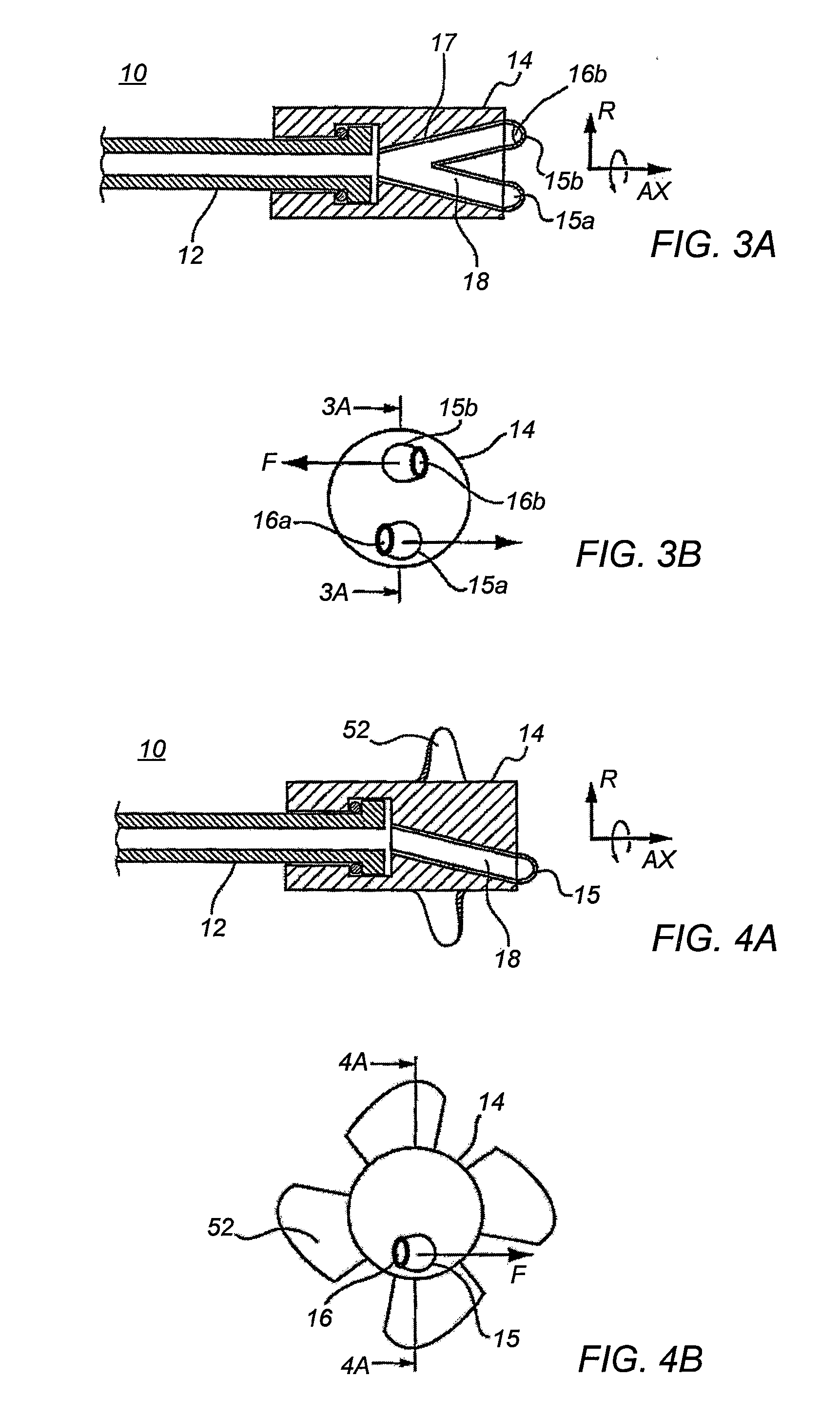
[0080]FIG. 3(a) is a partially longitudinally cross sectional schematic (side) view of an spray nozzle 10 showing the present invention and FIG. 3(b) is a front view of the same. FIG. 3(a) corresponds to a cross-section taken along the line 3A-3A of FIG. 3(b).

[0081]In the illustrated embodiment the pipe 17 embedded in the rotor 14 is divided into two sections which extend towards the distal end (at the right in the drawing) and bent at the distal end to form nozzle tips 15a, 15b having their respective outlet ports 16a, 16b.

[0082]In the drawing, upper and lower halves of the rotor 14 are arranged symmetrically with respect to the axis of rotation (AX). Accordingly, the two nozzle tips 15a, 15b with their respective outlet ports 16a, 16b are located symmetrically with respect to the axis of rotation. The lower outlet port 16a is opened in a direction intermediate between the axis of rotation and the leftward direction in FIG. 3(b). The upper outlet port 16b is opened in a direction ...

third embodiment

[0087]FIG. 4(a) is a partially longitudinally cross sectional schematic (side) view of a spray nozzle 10 showing the present invention and FIG. 4(b) is a front view of the same. FIG. 4(a) corresponds to a cross-section taken along the line 4A-4A of FIG. 4(b).

[0088]The illustrated embodiment is different from the first embodiment (FIG. 2) by the fact that the rotor 14 has an axially blowing fan 52 provided on the outer side thereof so that the fan 52 produces a flow of air along the axis of rotation (AX) as the rotor 14 is rotated by the ejection of the pressurized air.

[0089]Accordingly, in a case that the pressured air ejected along the radial direction (R) from the outlet port 16 is too great and that along the axis of rotation (AX) is smaller, the spray nozzle 10 of the third embodiment allows the fan 52 on the rotor 14 to produce an axial flow of which the counter force retards the rotating action of the rotor 14, hence increasing the force of the ejection along the axis of rotat...


PUM


Abstract

Provided is a spray nozzle, that includes a stationary tube and a rigid rotor. The stationary tube has a proximal, a distal end opposite the proximal end, and a tube passage that extends from substantially at or near the proximal end of the stationary tube to substantially at or near the distal end of the stationary tube. The stationary tube is configured to communicate substantially at or near the proximal end with a pressurized air source The rigid rotor has a distal end rotatably coupled substantially at or near the distal end of the stationary tube, a proximal end comprising an outlet port substantially at or near the proximal end and a rotor passage in fluid communication with the stationary tube. The rotor passage extends from substantially at or near the distal end of the rotor to substantially at or near the proximal end of the rotor. Further, the rotor passage is configured to remain in fluid communication with the tube passage during rotation of the rotor relative to the stationary tube about a rotor axis of rotation. The outlet port is offset a radial distance in a radial direction from the rotor axis substantially at or near at a distal end of the rotary member, and ejection of the pressurized air from the outlet port is configured to produce directional components of the pressurized air in the direction of rotation about the rotor axis of rotation.

Description

PRIORITY OF THE INVENTION[0001]This application claims priority to Japanese Patent Application No. 2007-228900 filed on Sep. 4, 2007 and Japanese Patent Application No. 2007-228901 filed on Sep. 4, 2007, which are herein incorporated by reference.BACKGROUND[0002]1. Field of the Invention[0003]The present invention relates to a rotary spray nozzle for ejecting or dispersing a jet of pressurized air, liquid, and / or other medium.[0004]2. Description of Related Art[0005]Many devices have been used for cleaning dust and dirt from a surface. Some such devices clean a surface by spraying a gas (e.g., compressed air) from an opening of a nozzle in a cleaning device. Other devices clean a surface by forcing a liquid, a powder, or a granular polishing agent through an opening of the device using a high-pressure air. Conventional device, therefore, tend to have a structure that forces high-pressure air and / or a cleaning fluid or other medium through a nozzle of the device.[0006]Japanese Patent...

Claims


Application Information

Patent Timeline
Patent Type & Authority Applications(United States)
IPC IPC(8): B05B7/00
CPCB05B3/022B05B3/0427B05B3/06B08B3/02B08B1/00B08B3/026B05B3/0409B05B7/2435B08B1/002
Inventor SENDO, SEIJI
Owner ECP INC
Why Eureka
Try Eureka