
Paper pick-up mechanism and feeder using the same

Active Publication Date: 2009-03-05
AVISION
View PDF16 Cites 0 Cited by
  • Summary
  • Abstract
  • Description
  • Claims
  • Application Information

AI Technical Summary

Benefits of technology

[0013]Still another object of the invention is to provide a paper pick-up mechanism, which is used in a feeder and has two one-way clutche

Problems solved by technology

However, the clutches are disposed outside the frame, so the clutches may interfere with other elements of the image forming apparatus or the feeder when the clutches are assembled in the image forming apparatus or the feeder.
Also, the two one-way clutches in series cannot be easily assembled with the multi-section rotating shaft.

Method used


Image

  • Paper pick-up mechanism and feeder using the same
  • Paper pick-up mechanism and feeder using the same
  • Paper pick-up mechanism and feeder using the same

Examples


Embodiment Construction

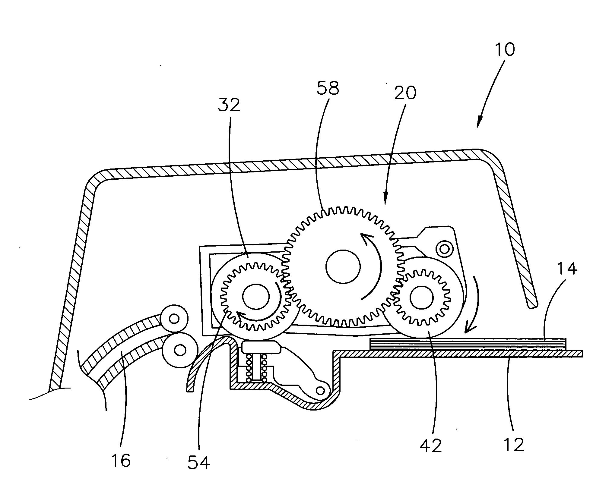
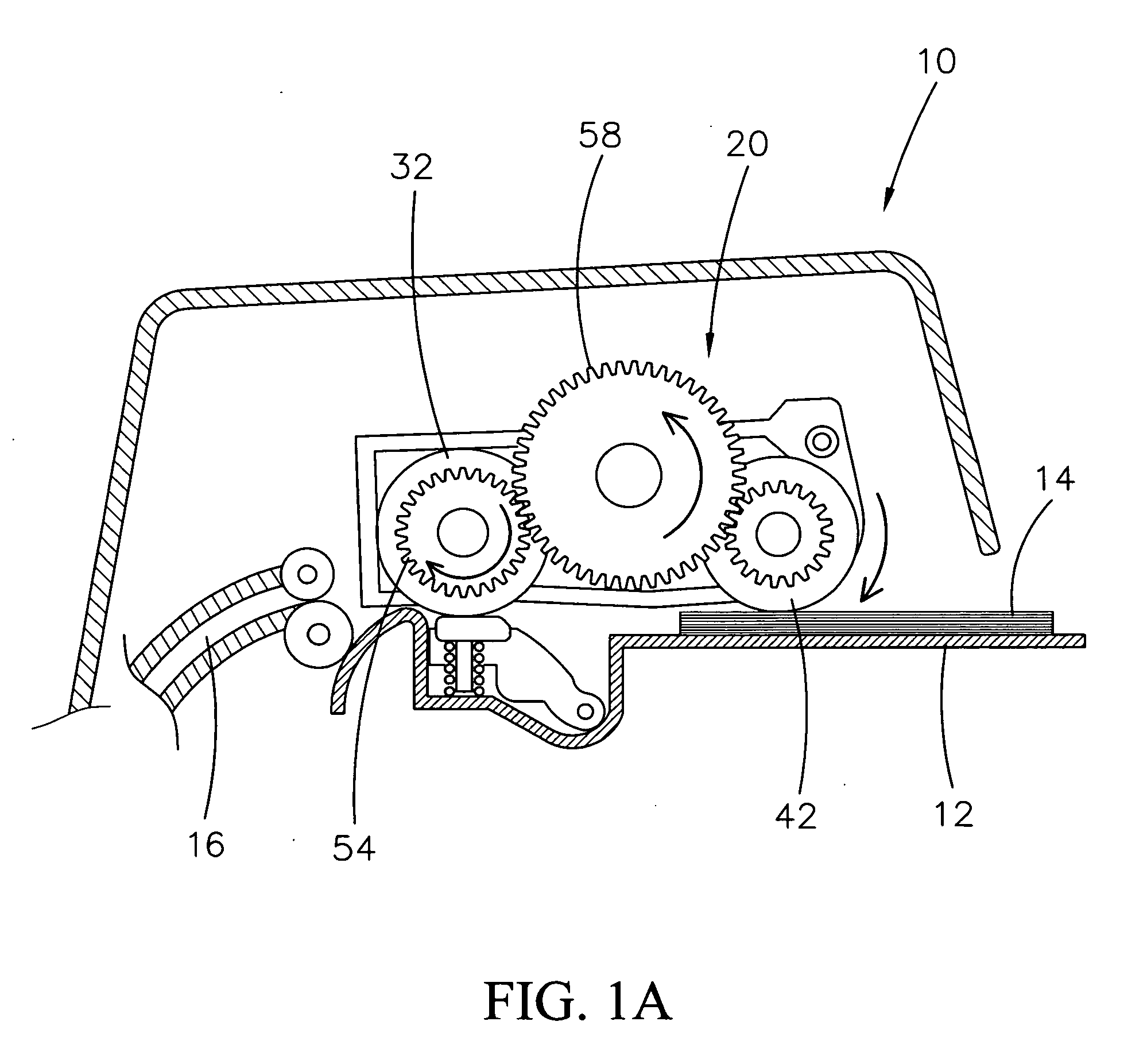
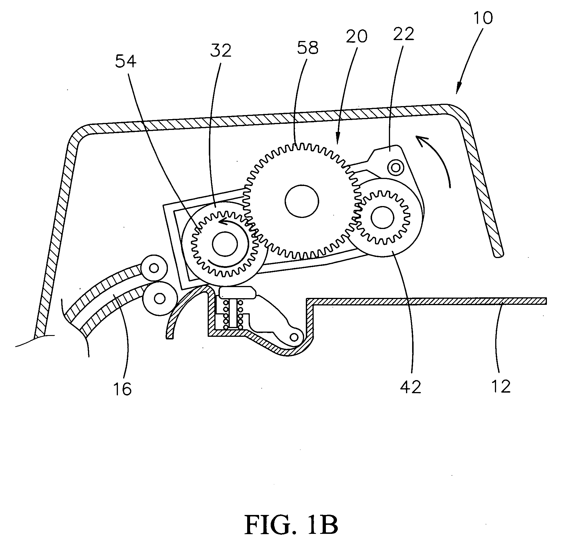
[0026]As shown in FIG. 1A, a pick-up mechanism 20 is disposed in a feeder 10. The feeder 10 can automatically and sequentially feed a stack of sheets 14 placed on a tray 12 into a sheet passageway 16 of the feeder 10. As shown in FIG. 1B, when the feeder 10 is in a non-sheet-feeding state, a pick-up roller 42 of the pick-up mechanism 20 is lifted away from the tray 12.

[0027]Referring to FIGS. 2 and 3, the pick-up mechanism 20 includes a frame 22, a separation roller 32, a transmission shaft 34, a pick-up roller 42, a pick-up roller shaft 44, a transmission gear shaft 59, and a gear set 52. The separation roller 32 and the pick-up roller 42 are respectively disposed on the transmission shaft 34 and the pick-up roller 42.

[0028]The frame 22 has two opposite walls 24 and 26 for supporting the transmission shaft 34, the pick-up roller shaft 44 and the transmission gear shaft 59. The separation roller 32 is located between the walls 24 and 26. The transmission shaft 34 receives a torque o...


PUM


Abstract

A paper pick-up mechanism for a feeder includes a pick-up roller, a pick-up roller shaft, a separation roller, a transmission shaft, a gear set and a transmission gear shaft. Two one-way clutches are respectively coupled to the transmission shaft and the transmission gear shaft in parallel. When the transmission shaft is rotated in a direction opposite to a sheet-feeding direction, the gear set, through the cooperation of the two one-way clutches are used as a planetary gear set to lift up the pick-up roller.

Description

BACKGROUND OF THE INVENTION[0001]1. Field of the Invention[0002]The invention relates in general to a paper pick-up mechanism, and more particularly to a paper pick-up mechanism for a feeder of an image forming apparatus. The image forming apparatus could be a scanner, a copier, a printer, a fax machine or a multi-function peripheral.[0003]2. Description of the Related Art[0004]A conventional feeder has a pick-up mechanism for sequentially feeding a stack of sheets placed on a tray.[0005]As shown in FIG. 8, The pick-up mechanism 90 includes a pick-up roller 91 and a separation roller 92. A motor (not shown) provides a torque to a rotating shaft 922 of the separation roller 92. A gear set 93 is disposed between the rotating shaft 912 of the pick-up roller 91 and a rotating shaft 922 of the separation roller 92 to transmit the torque to the pick-up roller 91. When the sheet-feeding operation is performed, the separation roller 92 and the pick-up roller 91 are rotated in a sheet-feedin...

Claims


Application Information

Patent Timeline
IPC IPC(8): B65H5/06
CPCB65H3/0684B65H2403/42B65H2403/72B65H2801/06B65H2220/09
Inventor SHENG, THOMASCHENG, SUNG-POCHEN, KU-MING
Owner AVISION
Features
  • Generate Ideas
  • Intellectual Property
  • Life Sciences
  • Materials
  • Tech Scout
  • Unparalleled Data Quality
  • Higher Quality Content
  • 60% Fewer Hallucinations
Learn More