Knee Walker

a walker and support technology, applied in the direction of steering devices, frictional rollers based transmission, cycle equipment, etc., can solve the problems of user loss of balance and fall, and achieve the effect of positive steering control and reduced effor

Active Publication Date: 2009-03-05
ESSENTIAL MEDICAL SUPPLY
View PDF29 Cites 30 Cited by
  • Summary
  • Abstract
  • Description
  • Claims
  • Application Information

AI Technical Summary

Benefits of technology

This patented design allows users to easily switch between different directions while reducing their efforts compared to traditional walking devices that require them constantly shift around or bending down during use. It also has features like automatic rollback mechanisms that prevent excess force when moving back again after being turned forward without any further input. Overall, this technology improves stability and safety for individuals who have difficulty controlling themselves movements due to lack of physical strength.

Problems solved by technology

The technical problem addressed in this patent is the difficulty and potential danger for users of previous knee walkers, which require the user to push the device with their good leg and may cause them to lose balance and fall. The patent aims to provide a solution to this problem by introducing a new device that eliminates the need for static handlebars and swiveling wheels.

Method used


Image

  • Knee Walker
  • Knee Walker
  • Knee Walker

Examples


Embodiment Construction

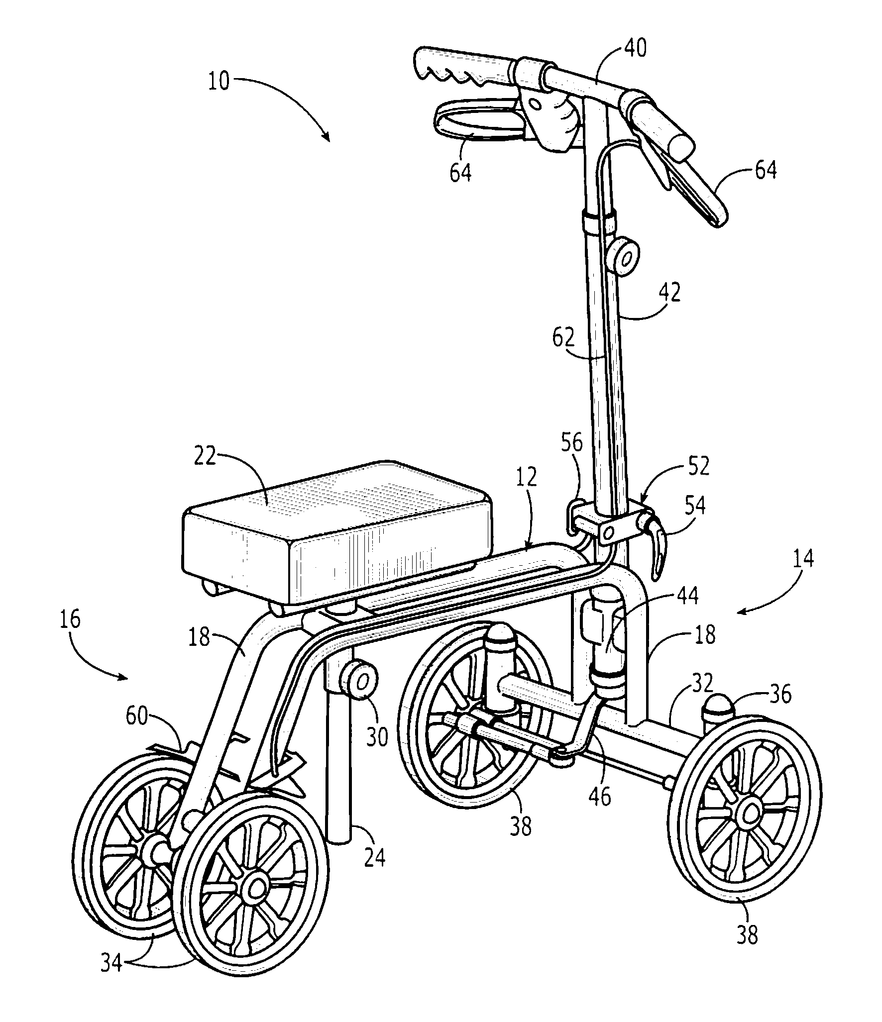
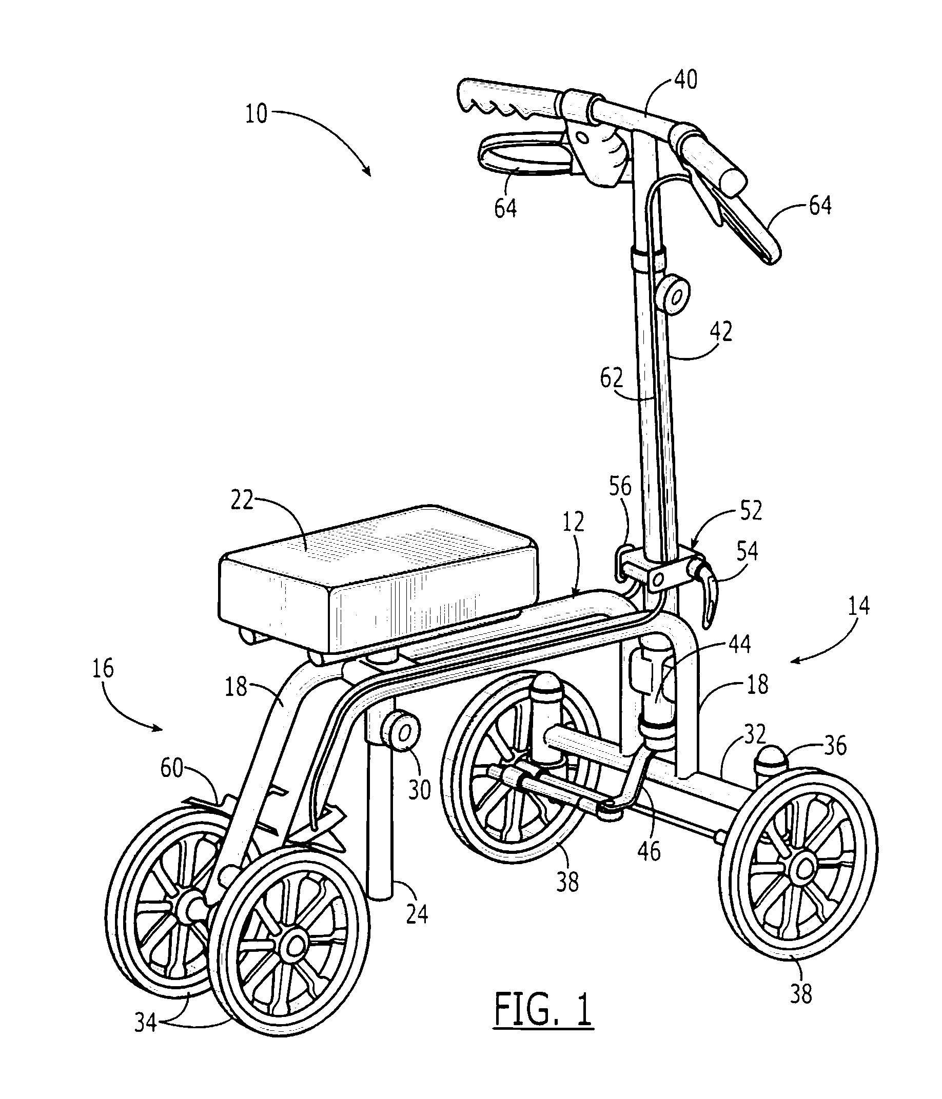
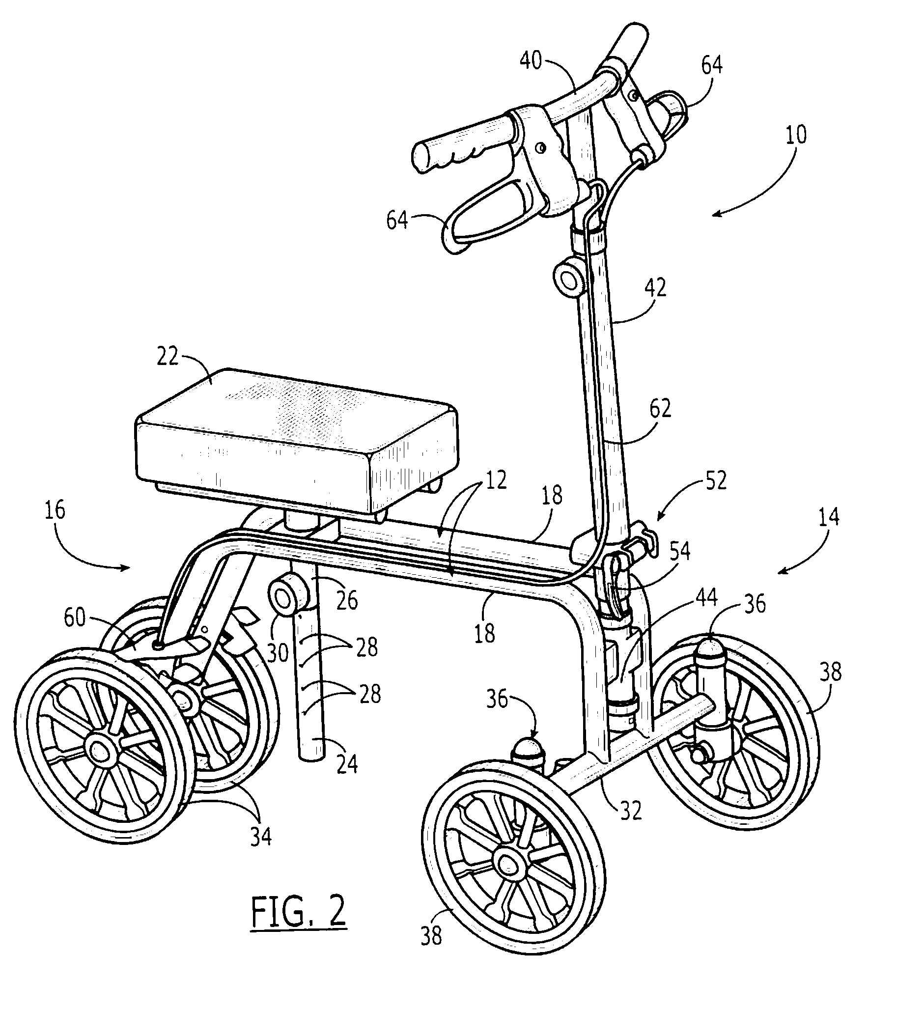
[0017]The present invention will now be described more fully hereinafter with reference to the accompanying drawings, in which preferred embodiments of the invention are shown. Unless otherwise defined, technical and scientific terms used herein have the same meaning as commonly understood by one of ordinary skill in the art to which this invention pertains. Although methods and materials similar or equivalent to those described herein can be used in the practice or testing of the present invention, suitable methods and materials are described below. In addition, the materials, methods and examples given are illustrative in nature only and not intended to be limiting. Accordingly, this invention may be embodied in many different forms and should not be construed as limited to the illustrated embodiments set forth herein. Rather, these illustrated embodiments are provided solely for exemplary purposes so that this disclosure will be thorough and complete, and will fully convey the sc...


PUM


Abstract

A knee walker includes a frame; a cushion; a front crossmember; two rear wheels; two front spindles and two front wheels each pivotally connected to one of the two front spindles. Positive steering is provided by a handlebar rotatably connected to the front end of the frame; a steering gear responsively engaged with the rotatably connected handlebar shaft; a steering arm actuated by the steering gear responsive to the handlebar; a steering rod connecting the steering arm and one of the two front spindles, so as to pivot one associated front wheel responsive to the steering arm; and a tie rod linking the two front spindles responsively to the steering rod.

Description


Claims


Application Information

Patent Timeline
Owner ESSENTIAL MEDICAL SUPPLY
Why Eureka
Try Eureka