Self-supported power generation device

a self-supporting, power generation device technology, applied in the direction of water-power plants, electric generator control, machines/engines, etc., can solve the problems of short supply of electrical power around the world, high maintenance and operation costs, and high system costs, so as to speed up water flow, high fuel expense, and high speed rotation

Inactive Publication Date: 2009-03-05
CHEN CHUN SHAN
View PDF0 Cites 41 Cited by
  • Summary
  • Abstract
  • Description
  • Claims
  • Application Information

AI Technical Summary

Benefits of technology

[0006]The primary purpose of the present invention is to provide a simple and self-supported power generation device that uses the altitude difference among floors of a building to speed up water flows and uses the increased speed of the water flows to drive high speed rotation of vanes of a power generator so as to simultaneously realize high speed rotation and low power generation of electrical power of multiple sets of power generators and to provide continuous power generation through vertical stacked arrangement of the multiple sets of electrical power generators so as to establish a practical and simple self-supported power generation device.
[0007]In view of the drawbacks of the conventional gasoline/diesel engine bas

Problems solved by technology

Due to the increased consumption of electrical power, the supply of electrical power is getting short around the world.
Such systems are expensive and the maintaining and operation costs are also very high due to the high costs of gasoline and diesel.
In addition, these private power generation systems are only put into operation in case of emergencies to temporarily supply power to the fire-fighting and public utility systems.
Apparently, such systems are not actually practical.
This is troublesome to the residents of the building and may cause building safety problems.
For the currently available gasoline or diesel engines, the purcha

Method used


Image

  • Self-supported power generation device
  • Self-supported power generation device
  • Self-supported power generation device

Examples


Embodiment Construction

[0012]The following descriptions are of exemplary embodiments only, and are not intended to limit the scope, applicability or configuration of the invention in any way. Rather, the following description provides a convenient illustration for implementing exemplary embodiments of the invention. Various changes to the described embodiments may be made in the function and arrangement of the elements described without departing from the scope of the invention as set forth in the appended claims.

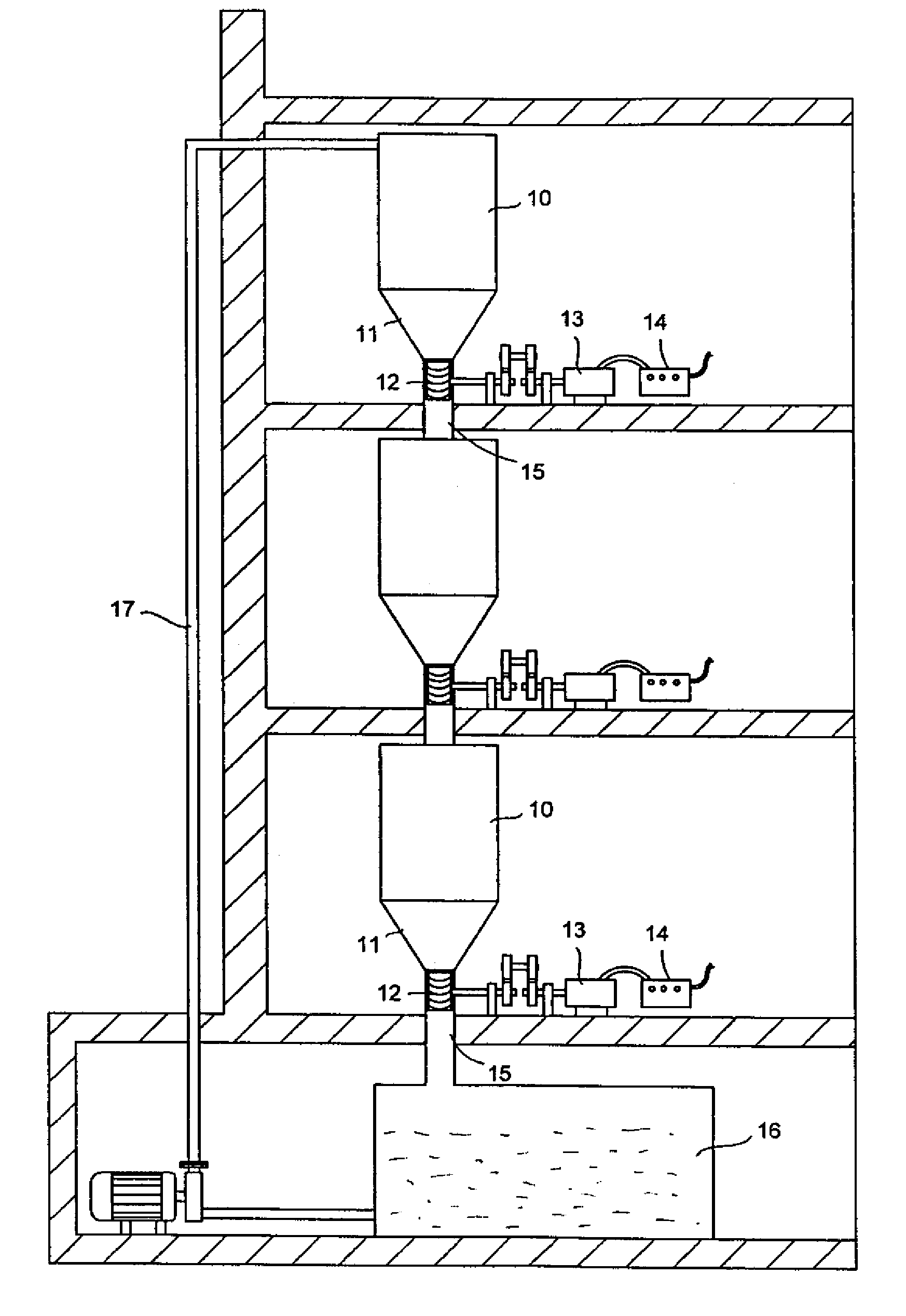
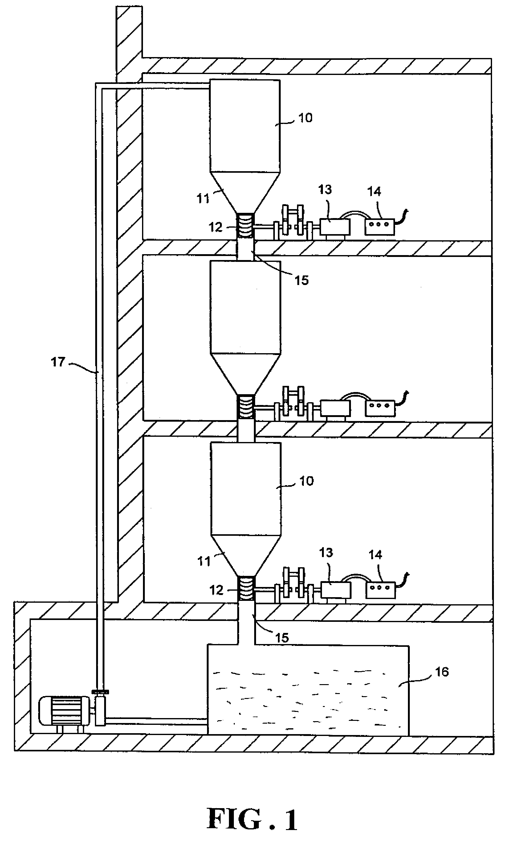
[0013]With reference to the drawings and in particular to FIG. 1, which shows an overall arrangement of a self-supported power generation device constructed in accordance with the present invention, the self-supported power generation device is operated on the basis of altitude difference provided by the height of a building and can be accommodated in a space provided by about three floors / stories of the building, which leads to a vertical height difference of approximately 12 to 16 meters. The a...


PUM


Abstract

A self-supported power generation device is installed in a high building having multiple floors to realize self-supported power supply of low power and simplified arrangement. Water reservoir is arranged in a floor-spaced manner by tanks set in different floors. Each tank has a conic converged lower section forming a discharge opening coupled to a power generator unit that is driven by vanes to generate electrical power. Thus, by the water head supplied from each tank to drive the vanes for rotating the power generator unit, and with a vertical stacked manner of the multiple sets of power generator units and tanks, a multi-floor water-weight-driven power generation assembly is established. A water collection reservoir is provided at the bottommost location to collect the water for cyclic use. Thus, self-supported power generation for self-supported supply of power of a building is realized and environmental protection and healthy concerns are also satisfied.

Description

BACKGROUND OF THE INVENTION[0001](a) Technical Field of the Invention[0002]The present invention relates to a simplified self-supported power generation device, and in particular to a simplified power generation device that bases on difference of altitude among different floors in a high building to generate water flows from tanks caused by gravity to drive vanes for rotation in order to effect power generation and supply of the power so generated, together with a vertically-stacked multi-set arrangement to realize continuous power generation, wherein the power so generated are collected and properly distributed for public use of the building to ensure safety, convenient, and environment-conservative supplement of electrical power.[0003](b) Description of the Prior Art[0004]Electrical power has been commonly and widely used all over the world to power all kinds of electrical appliances. Due to the increased consumption of electrical power, the supply of electrical power is getting s...

Claims


Application Information

Patent Timeline
IPC IPC(8): E02B9/00
CPCF03B17/005F03G7/10Y02E10/20F05B2240/911F05B2250/232F05B2240/40
Inventor CHEN, CHUN-SHAN
Owner CHEN CHUN SHAN
Why Eureka
Try Eureka