Wall switch for lighting load management system for lighting systems having multiple power circuits

Inactive Publication Date: 2009-03-05
SQUARE D CO
View PDF13 Cites 35 Cited by
  • Summary
  • Abstract
  • Description
  • Claims
  • Application Information

AI Technical Summary

Benefits of technology

[0008]At least two manually operable switches are coupled to the microcontroller to provide the microcontroller with ON and OFF command signals for at least two of the lamp groups powered by different power circuits, and a separate status indicator light associated with each of the switches provides an indication of whether the lamp group associated with each switch is currently ON or OFF. In one implementation, each of the status indicator lights is automatically illuminated by signal from the microcontroller when its associated lamp group is ON thereby giving a direct visual indication of which power circuit and lamp group has been activated by the automatic illumination control. By indicating the status of power control, the occupant is not likely to accidentally turn off the powered lights. Thus, wear on the

Problems solved by technology

The use of multiple power circuits in combination with an automatic lighting control management system can give rise to situations where it is difficult for a user to intervene with the desired manual control.
For example, a user may be in an illuminated space where it is difficult to determine visually which of two or more ban

Method used


Image

  • Wall switch for lighting load management system for lighting systems having multiple power circuits
  • Wall switch for lighting load management system for lighting systems having multiple power circuits
  • Wall switch for lighting load management system for lighting systems having multiple power circuits

Examples


Example

[0022]Although the invention will be described in connection with certain preferred embodiments, it will be understood that the invention is not limited to those particular embodiments. On the contrary, the invention is intended to cover all alternatives, modifications, and equivalent arrangements as may be included within the spirit and scope of the invention as defined by the appended claims.

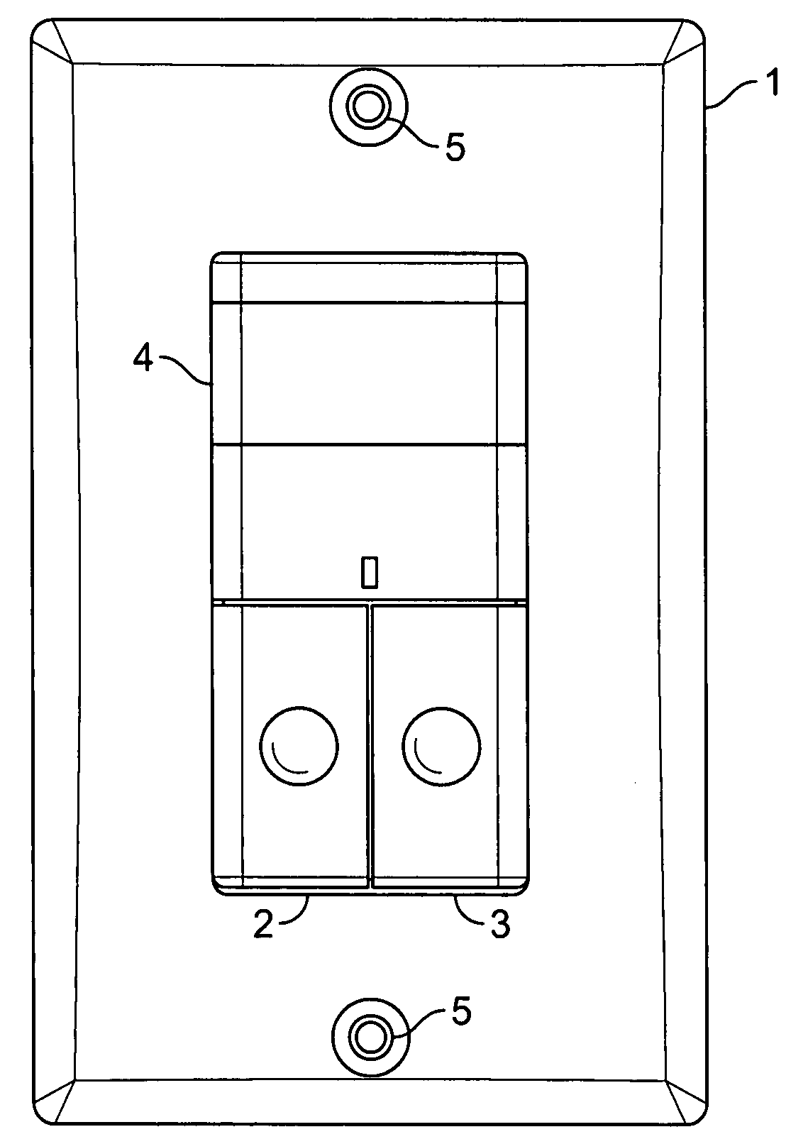
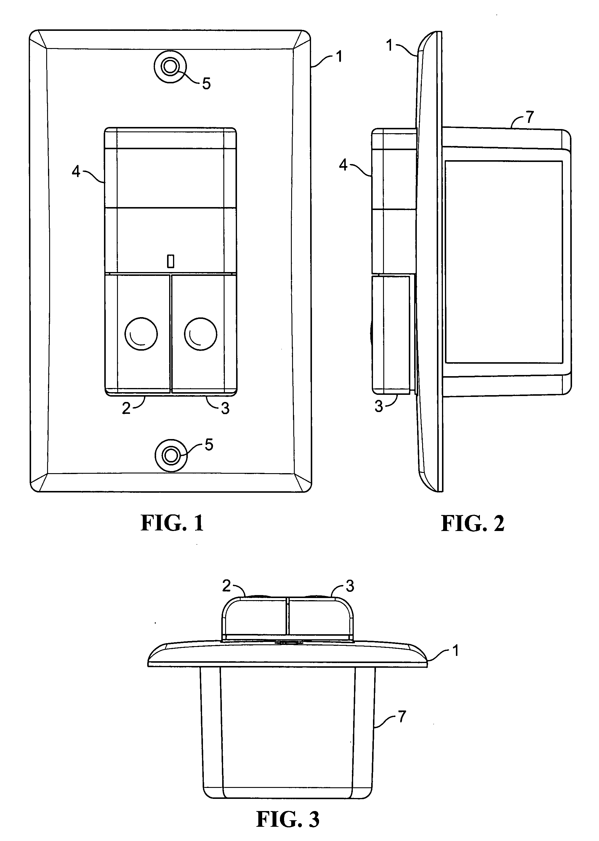
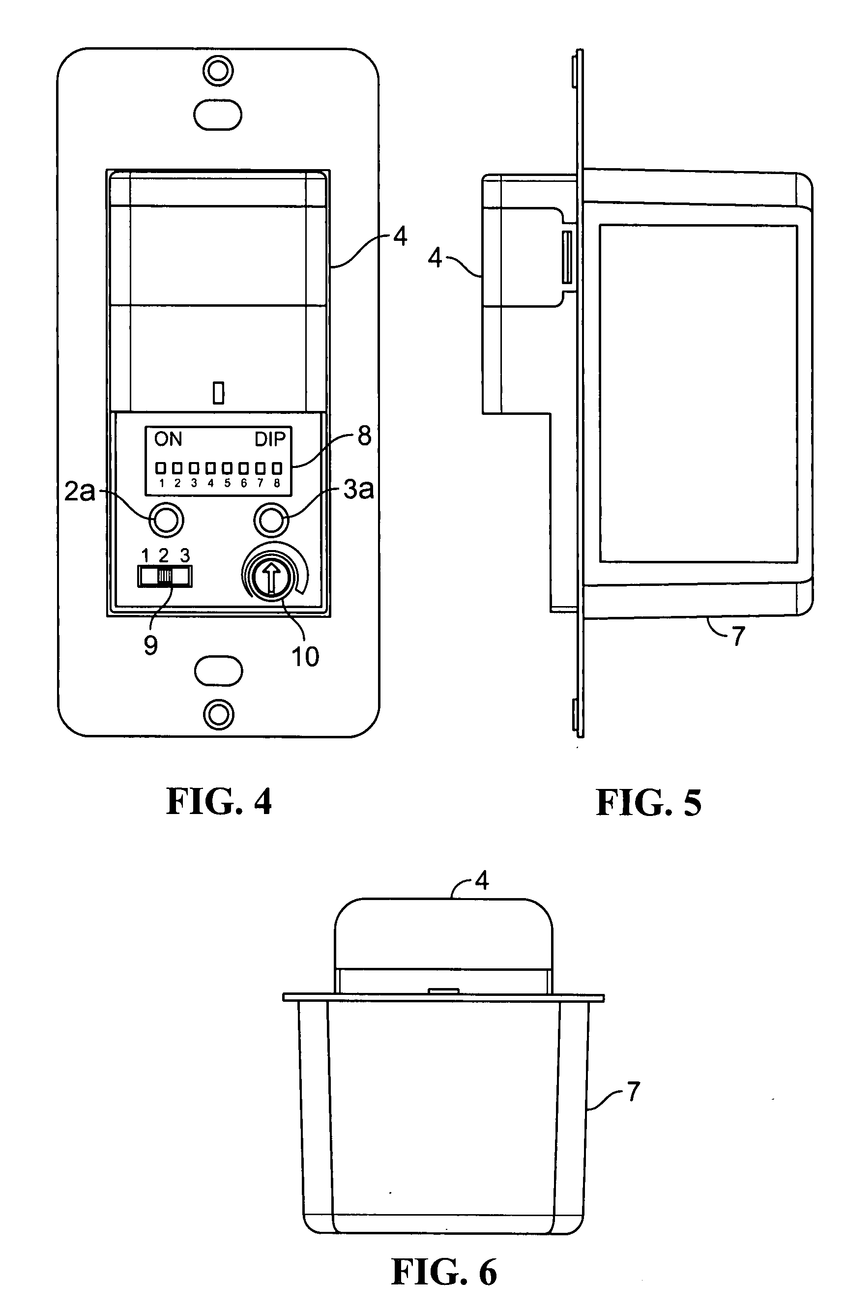
[0023]Turning now to the drawings and referring first to FIGS. 1-3, a wall plate 1 surrounds a control unit that includes a pair of pushbuttons 2 and 3 and a transparent cover 4 for the lens of a motion sensor for detecting motion within a space having artificial illumination. The plate 1 forms a pair of holes 5 for receiving a pair of screws to attach the plate 1 to a wall. FIGS. 4-6 show the same control unit shown in FIGS. 1-3 with the wall plate 1 and the covers of the pushbuttons 2 and 3 removed, revealing the underlying metal frame 6 and control unit 7. As seen most clearly in FIG. 4, th...


PUM


Abstract

A wall switch is provided for an automatic lighting control system for a space equipped with multiple lamps for illuminating the space and multiple power circuits for supplying power to different groups of said lamps. The wall switch includes at least one sensor detecting conditions or events that indicate that increased illumination of the space by the lamps is needed or decreased illumination of the space by the lamps is allowable. Normal control of the electric lighting is thus automatic to a large degree. But, at least two manually operable switches are coupled to the microcontroller to provide the microcontroller with ON and OFF command signals for at least two of the lamp groups powered by different power circuits. A separate status indicator light for each of the switches is controlled by the wall switch and provides an indication of whether the lamp group associated with each manual switch is currently ON or OFF as a safety and economy feature.

Description

FIELD OF THE INVENTION[0001]The present invention relates to a wall switch for use with a lighting load management system for lighting systems having multiple power circuits and that automatically turn lights ON and / or OFF in response to control signals from sensors that detect whether a space is occupied or not occupied.BACKGROUND OF THE INVENTION[0002]Automatic shut-off lighting controls are used to save electrical energy, and are often required by legislated energy codes. Today's control devices have multiple control outputs which are used to operate multiple lighting circuits in a particular area. The advantage of having multiple circuits feeding an area is that multiple levels of light can be achieved by selecting the number of circuits that are ON simultaneously. This multiple-level ability is also required by some energy codes so that lower levels of artificial illumination can be provided in an occupied area.[0003]The type and arrangement of light fixtures is a factor in the...

Claims


Application Information

Patent Timeline
IPC IPC(8): H01H35/00
CPCH05B37/0227Y02B20/42H05B37/0281H05B47/115H05B47/16Y02B20/40
Inventor REID, DREW A.STOTTLEMYER, WILLIAM O.
Owner SQUARE D CO
Why Eureka
Try Eureka