Method of correcting image distortion and apparatus for processing image using the method

a technology of image distortion and processing apparatus, applied in the field of image correction, can solve the problems of resolution degradation, radial distortion increase reduce the resolution from the center to the outer portions of the lens, so as to reduce blurring and remove jagged edges

Inactive Publication Date: 2009-03-05
CORELOGIC
View PDF17 Cites 33 Cited by
  • Summary
  • Abstract
  • Description
  • Claims
  • Application Information

AI Technical Summary

Benefits of technology

[0017]The distortion correcting unit may correct radial distortion that is caused by the wide-angle lens through backward mapping using the distortion coefficient. The distortion correcting unit may remove jagged-edge artifacts caused by the correcting of the radial distortion by using a bilinear interpolation.
[0018]The image processing unit may further comprise a curve fitting unit for fitting a curve at the outer portions in order to minimize the blurring at the outer portions of the corrected image. The curve fitting unit may select a plurality of points based on an inflection point in an RC-RD graph and fit the curve at the outer portions using a cubic equation.

Problems solved by technology

A wide-angle lens allows a wide angle of view, but has a disadvantage in that resolution decreases from the center to outer portions of the lens.
The wide-angle lens also has a disadvantage in that radial distortion increases from the center to the outer portions of the lens.
Such radial distortion is a main cause of resolution degradation.
In addition, the metric method may introduce severe measurement errors that occur when the intrinsic and extrinsic parameters are obtained.
However, in the non-metric method, the distortion coefficients can be measured only when the image contains an object having linear components.
In addition, automatic distortion correcting algorithms are very sensitive to noise in the non-metric method.

Method used


Image

  • Method of correcting image distortion and apparatus for processing image using the method
  • Method of correcting image distortion and apparatus for processing image using the method
  • Method of correcting image distortion and apparatus for processing image using the method

Examples


Embodiment Construction

[0029]It should be understood that when an element is described as being connected to another element, the elements may be directly connected, or an intervening element may exist between the two elements. In the following description of the present invention, the sizes of elements shown in the drawings may be exaggerated, if needed, or an element may be omitted from the drawing for a better understanding of the present invention. Like reference number refer to like element throughout the drawings. Terms used are intended to depict the exemplary embodiments and should not be interpreted as limiting the intended scope of the claims.

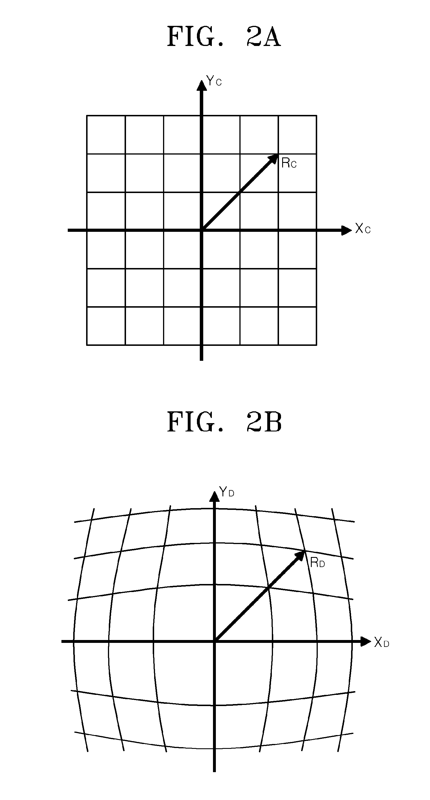
[0030]FIGS. 2A and 2B are the plane coordinate systems showing the radial distortion caused by a wide-angle lens. FIG. 2A illustrates a coordinate system of a corrected image. FIG. 2B illustrates a coordinate system of an image with radial distortion that is caused by a wide-angle lens. The radial distortion caused by a wide-angle lens increases farther awa...


PUM


Abstract

A method of correcting image distortion and an apparatus for processing an image using the method are provided, where the method can overcome the disadvantages of the conventional methods of correcting lens distortion and can minimize image quality degradation at outer portions,. The method includes: receiving an image from a wide-angle lens; extracting a distortion coefficient of the distortion in the image caused by the wide-angle lens; correcting the distortion of the image by using the extracted distortion coefficient; and displaying a corrected image. The apparatus includes: a wide-angle lens for receiving an image; an image processing unit comprising a distortion coefficient extracting unit for extracting a distortion coefficient of distortion in the image caused by the wide-angle lens and a distortion correcting unit for correcting the distortion of the image using the extracted distortion coefficient; and a display unit for displaying a corrected image.

Description

CROSS-REFERENCE TO RELATED PATENT APPLICATION[0001]This application claims the benefit of Korean Patent Application No. 10-2007-0086274, filed on Aug. 27, 2007, in the Korean Intellectual Property Office, the disclosure of which is incorporated herein in its entirety by reference.FIELD OF THE INVENTION[0002]The present invention relates to a method and apparatus for processing an image, and particularly, to a method of correcting image distortion and an apparatus for processing an image using the method.BACKGROUND OF THE INVENTION[0003]Cameras have been used in a wide range of industrial applications and are being used in an increasingly larger number of applications. For example, cameras are used in place of human eyes in many automatic industrial applications, including monitoring of robots on an assembly line, product quality testing, medical diagnosis, security, and recognition of an image captured by an imaging system.[0004]In general, when a high resolution image needs to be o...

Claims


Application Information

Patent Timeline
Patent Type & Authority Applications(United States)
IPC IPC(8): H04N5/217G06T3/00H04N5/232
CPCH04N5/217H04N23/81H04N9/28H04N3/23
Inventor KWON, SUNG JIN
Owner CORELOGIC
Why Eureka
Try Eureka