Method for manufacturing a thin closure magnetic head

Active Publication Date: 2009-03-05
IBM CORP
View PDF6 Cites 4 Cited by
  • Summary
  • Abstract
  • Description
  • Claims
  • Application Information

AI Technical Summary

Benefits of technology

[0018]An embodiment of the invention comprises a method of manufacturing thin closure magnetic read / write heads, such as magnetic tape heads. The method reduces flexural strain in the closure during fabrication of mini-chiplet heads, so that closure fabrication may have better yield and closure thickness can be reduced.
[0019]An array comprising several rows, with each row comprising a chip, where each chip comprises primarily active devices, is fabricated on a wafer. Each chip may contain read or write elements or both. Closure strips are attached to each row of the array using known methods. The closure strips span only the length of a row, so that the closures are not subjected to flexure during subsequent processing steps. The closures then may be lapped relatively thin, since exposure of the closures due to flexure during subsequent processing is mitigated.
[0020]Once the closures are lapped, a side bar is bonded to a side of the array to form a column. The side bar is dimensioned to provide a column with dimensions similar to prior art columns, when bonded to the array. In one embodiment, a side bar is bonded to each side of the array and to ends of the closures, to form a column with dimensions similar to prior art columns. This allows columns manufactured by the invention to undergo additional processing using existing processes.

Problems solved by technology

As the tape passes between the write and read modules, the tape can “mistrack”, where data is written to or read from the wrong data track, due to the tape skewing as is passes across the gap between the read and write modules.
Due to their length and small dimensions, the closures 302 are mechanically fragile.
With thicknesses in the range of about 25 to 50 micrometers anticipated in the future, the closures may be more fragile.

Method used


Image

  • Method for manufacturing a thin closure magnetic head
  • Method for manufacturing a thin closure magnetic head
  • Method for manufacturing a thin closure magnetic head

Examples


Embodiment Construction

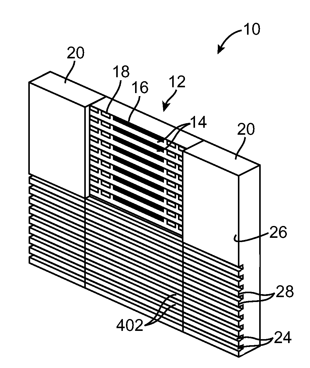
[0038]A method of manufacturing thin closure magnetic read / write heads, such as magnetic tape heads. The method reduces flexure of the closure during processing of the head, so that breakage of the closure during fabrication of the heads is mitigated and closure thickness can be reduced. A mini-chiplet array of chips is fabricated on a wafer. The array is closed, with a closure strip bonded to each row of the array. A closure strip spans only the length of the row, so that the closures are not subjected to flexure during processing. This allows for the closures to be lapped very thin. Side bars are bonded to the array to form a column with dimensions similar to prior art columns. This allows columns manufactured by the invention to undergo additional processing using existing processes.

[0039]Referring to FIG. 6 and FIG. 7, there is shown, generally at 10, a partially constructed mini-chiplet column, fabricated according to one embodiment of the invention. The invention comprises a m...


PUM

PropertyMeasurementUnit
Thicknessaaaaaaaaaa
Thicknessaaaaaaaaaa
Thicknessaaaaaaaaaa

Abstract

A method of manufacturing thin closure magnetic read / write heads, such as magnetic tape heads is provided. The method provides improved flexural strength of the closure so that the closure breakage during fabrication of the heads is mitigated and closure thickness is reduced. An array of chips is fabricated on a wafer. The array is closed, with a closure strip bonded to each row of the array. Closures span only the length of a row, so that the closures are not subjected to flexure during processing and breakage due to flexure is mitigated. Side bars are bonded to the array to form a column with dimensions similar to prior art columns. This allows columns manufactured by the invention to undergo additional processing using existing processes.

Description

BACKGROUND OF THE INVENTION[0001]1. Field of the Invention[0002]The present invention relates to magnetic head fabrication, and more particularly, to an improved method of manufacturing thin closure magnetic read / write heads.[0003]2. Background Information[0004]Nonvolatile storage media technologies, such as magnetic discs, magnetic tape cartridges, and optical disk cartridges are well known. Data storage technology is continually pushed to increase storage capacity and reliability. Decreased bit dimensions have lead to increased data storage densities in magnetic storage media, such as magnetic tape.[0005]Thus, improvement in magnetic medium data storage capacity is achievable, in part, from improvements in the magnetic head assemblies used for reading and writing data on the magnetic storage media. More data tracks on the magnetic tape are made possible by reducing the feature sizes of read and write elements of the head, such as by using thin-film fabrication techniques, to build...

Claims


Application Information

Patent Timeline
IPC IPC(8): G11B5/127
CPCG11B5/102G11B5/3169G11B5/3173Y10T29/49046Y10T29/49052Y10T29/49048Y10T29/49021Y10T29/49043Y10T29/49032Y10T29/49044
Inventor BISKEBORN, ROBERT G.LO, CALVIN S.
Owner IBM CORP
Why Eureka
Try Eureka