Magnetic head for perpendicular magnetic recording and method of manufacturing same

a perpendicular magnetic and magnetic recording technology, applied in the direction of magnetic recording heads, data recording, instruments, etc., can solve the problems of affecting the quality of the magnetic recording, so as to prevent the problem and improve the write characteristics

Active Publication Date: 2009-03-05
HEADWAY TECH INC
View PDF23 Cites 87 Cited by
  • Summary
  • Abstract
  • Description
  • Claims
  • Application Information

AI Technical Summary

Benefits of technology

[0019]It is an object of the present invention to provide a magnetic head for perpendicular magnetic recording that is capable of preventing the problems resulting from the skew and attaining improved write characteristics, and to provide a method of manufacturing such a magnetic head.
[0041]According to the magnetic head for perpendicular magnetic recording or the method of manufacturing the same of the present invention, the top surface of the pole layer includes the first portion and the second portion, and the distance from the substrate to an arbitrary point on the first portion increases with increasing distance from the medium facing surface to the arbitrary point. The angle of inclination of the first portion taken at the arbitrary point with respect to the direction perpendicular to the medium facing surface increases stepwise or continuously with increasing distance from the medium facing surface to the arbitrary point. The angle of inclination taken at the first edge is greater than zero degree. As a result, according to the present invention, it is possible to prevent the problems resulting from the skew, and to improve the write characteristics by introducing magnetic flux of great magnitude to the medium facing surface through the pole layer. According to the present invention, the angle of inclination of the first portion taken at an arbitrary point on the first portion with respect to the direction perpendicular to the medium facing surface increases stepwise or continuously with increasing distance from the medium facing surface to the arbitrary point. Consequently, according to the present invention, a variation in write characteristics that would occur in response to a variation in the position of the medium facing surface is moderate.

Problems solved by technology

On the other hand, if the track width is reduced, the write characteristics, such as an overwrite property that is a parameter indicating an overwriting capability, suffer degradation.
However, as the neck height gets smaller, it becomes difficult to precisely define the track width.
It is difficult to precisely form a portion of the side surface of the pole layer near the boundary between the track width defining portion and the wide portion.
As a result, as the neck height gets smaller, it becomes difficult to precisely define the width of the end of the track width defining portion located in the medium facing surface, that is, the track width.
In a magnetic disk drive of the perpendicular magnetic recording system, in particular, which exhibits a better capability of writing on a recording medium compared with the longitudinal magnetic recording system, if the above-mentioned skew occurs, there arise problems such as a phenomenon in which, when data is written on a certain track, data stored on a track adjacent thereto is erased (this is hereinafter called adjacent track erasing), or unwanted writing performed between two adjacent tracks.
As a result, the pole layer becomes unable to introduce magnetic flux of great magnitude to the medium facing surface, and this leads to degradation of overwrite property.
In this case, however, the following problem can occur.
In the portion in which the thickness abruptly changes, flux leakage from the pole layer is likely to occur.
As a result, the effective track width can increase and the foregoing problems resulting from the skew can occur.
On the other hand, if the distance from the medium facing surface to the boundary between the first and the second portion is small, a problem described below can occur.
For the foregoing reasons, conventionally, it has been difficult to prevent the problems resulting from the skew and to improve the write characteristics.

Method used


Image

  • Magnetic head for perpendicular magnetic recording and method of manufacturing same
  • Magnetic head for perpendicular magnetic recording and method of manufacturing same
  • Magnetic head for perpendicular magnetic recording and method of manufacturing same

Examples


first embodiment

[0071]Embodiments of the present invention will now be described in detail with reference to the drawings. Reference is first made to FIG. 4 and FIG. 5 to describe the configuration of a magnetic head for perpendicular magnetic recording of a first embodiment of the invention. FIG. 4 is a front view of the medium facing surface of the magnetic head for perpendicular magnetic recording of the embodiment. FIG. 5 is a cross-sectional view for illustrating the configuration of the magnetic head for perpendicular magnetic recording of the embodiment. FIG. 5 illustrates a cross section perpendicular to the medium facing surface and the top surface of the substrate. In FIG. 5 the arrow marked with T shows the direction of travel of a recording medium.

[0072]As illustrated in FIG. 4 and FIG. 5, the magnetic head for perpendicular magnetic recording (hereinafter simply called the magnetic head) of the embodiment includes: a substrate 1 made of a ceramic material such as aluminum oxide and tit...

second embodiment

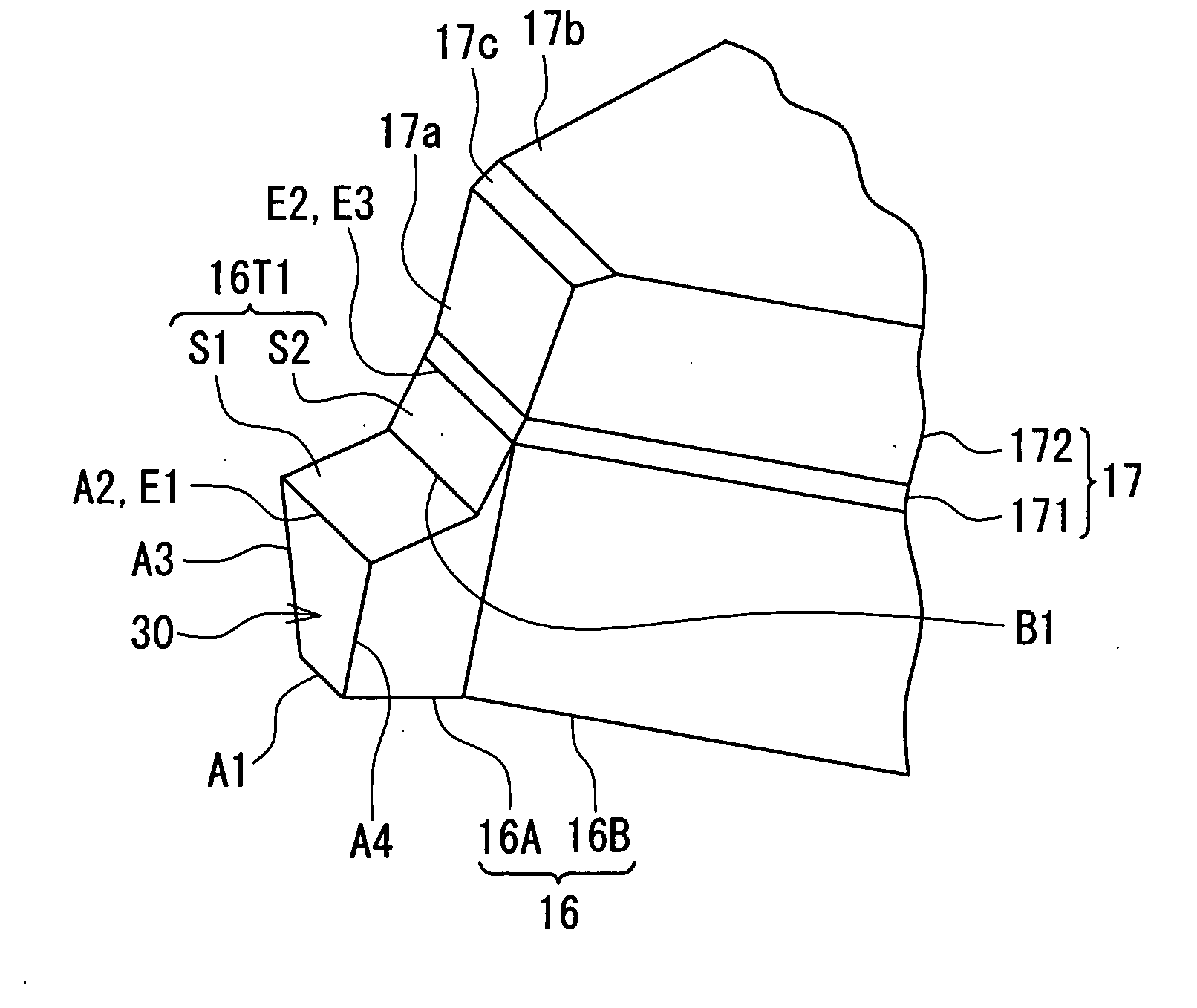
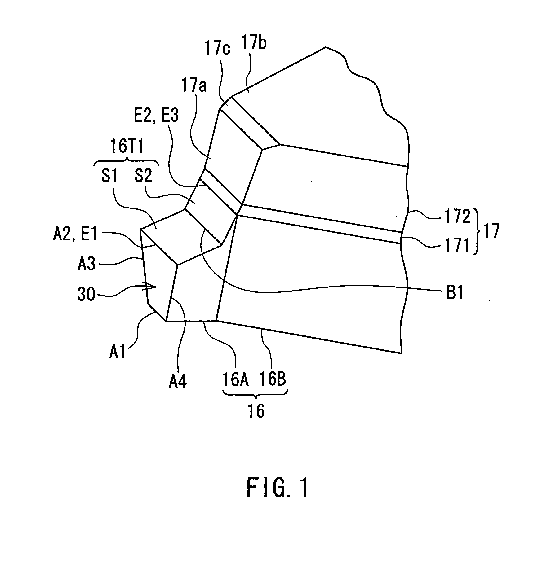
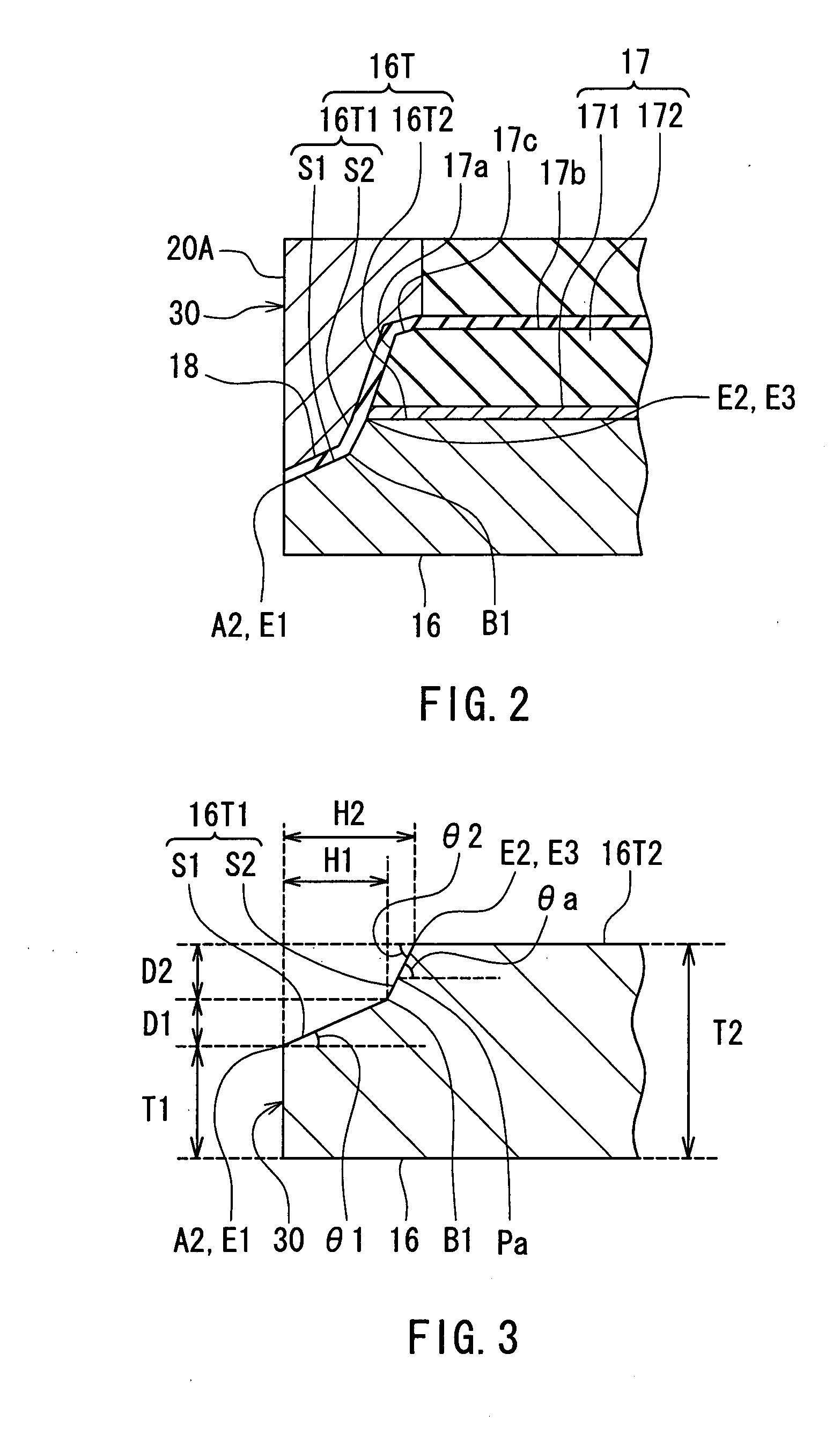
[0163]A magnetic head and a method of manufacturing the same of a second embodiment of the invention will now be described. Reference is now made to FIG. 21 to FIG. 23 to describe the configuration of the magnetic head of the second embodiment. FIG. 21 is a perspective view illustrating respective portions of the pole layer 16 and the nonmagnetic layer 17 of the embodiment near the medium facing surface 30. FIG. 22 is a cross-sectional view illustrating respective portions of the pole layer 16, the nonmagnetic layer 17, the gap layer 18 and the shield 20 of the embodiment near the medium facing surface 30. FIG. 23 is a cross-sectional view of a portion of the pole layer 16 of the embodiment near the medium facing surface 30.

[0164]In the second embodiment, both of the second flat surface portion S2 of the first portion 16T1 of the top surface 16T of the pole layer 16 and the front end face 17a of the nonmagnetic layer 17 are formed into flat surfaces that are substantially parallel t...

third embodiment

[0175]A magnetic head and a method of manufacturing the same of a third embodiment of the invention will now be described. Reference is now made to FIG. 27 and FIG. 28 to describe the configuration of the magnetic head of the third embodiment. FIG. 27 is a cross-sectional view illustrating respective portions of the pole layer 16, the nonmagnetic layer 17, the gap layer 18 and the shield 20 of the embodiment near the medium facing surface 30. FIG. 28 is a cross-sectional view of a portion of the pole layer 16 of the embodiment near the medium facing surface 30.

[0176]In the third embodiment, the first portion 16T1 of the top surface 16T of the pole layer 16 does not include any flat surface portion, so that the entire first portion 16T1 is formed into a recessed curved surface. The angle of inclination of the first portion 16T1 taken at an arbitrary point on the first portion 16T1 with respect to the direction perpendicular to the medium facing surface 30 increases continuously with ...


PUM

PropertyMeasurementUnit
angle of inclinationaaaaaaaaaa

Abstract

A top surface of a pole layer of a magnetic head includes: a first portion having a first edge located in a medium facing surface and a second edge opposite thereto; and a second portion located farther from the medium facing surface than the first portion and connected to the first portion at the second edge. The distance from a substrate to an arbitrary point on the first portion increases with increasing distance from the medium facing surface to the arbitrary point. The angle of inclination of the first portion taken at the arbitrary point with respect to a direction perpendicular to the medium facing surface increases stepwise or continuously with increasing distance from the medium facing surface to the arbitrary point. The angle of inclination taken at the first edge is greater than zero degree. The second portion extends in a direction substantially perpendicular to the medium facing surface.

Description

BACKGROUND OF THE INVENTION[0001]1. Field of the Invention[0002]The present invention relates to a magnetic head for perpendicular magnetic recording that is used for writing data on a recording medium by means of a perpendicular magnetic recording system, and to a method of manufacturing such a magnetic head.[0003]2. Description of the Related Art[0004]The recording systems of magnetic read / write devices include a longitudinal magnetic recording system wherein signals are magnetized in the direction along the surface of the recording medium (the longitudinal direction) and a perpendicular magnetic recording system wherein signals are magnetized in a direction perpendicular to the plane of the recording medium. It is known that the perpendicular magnetic recording system is harder to be affected by thermal fluctuation of the recording medium and capable of implementing higher linear recording density, compared with the longitudinal magnetic recording system.[0005]Typically, magnetic...

Claims


Application Information

Patent Timeline
Patent Type & Authority Applications(United States)
IPC IPC(8): G11B5/127
CPCG11B5/1278Y10T29/49046G11B5/3163G11B5/3116
Inventor SASAKI, YOSHITAKAITOH, HIROYUKIARAKI, HIRONORITANEMURA, SHIGEKIISHIZAKI, KAZUOHORINAKA, TAKEHIRO
Owner HEADWAY TECH INC
Why Eureka
Try Eureka