Ram macro and timing generating circuit thereof

a timing generation circuit and macro technology, applied in the field of timing generating circuits, can solve the problems of difficulty in identifying whether a fault is present, the operation timing of various types of control signals output from the testing circuit cannot be conventionally changed, and it is difficult to adjust the mutual timing of the two types of external input clock signals, etc., to achieve the effect of easy changing the operation timings

Inactive Publication Date: 2009-03-05
FUJITSU LTD
View PDF13 Cites 12 Cited by
  • Summary
  • Abstract
  • Description
  • Claims
  • Application Information

AI Technical Summary

Benefits of technology

[0016]An object of the present invention is to provide a timing generating circuit that can make either of operation margins of read and write operations strict, can thereby identify whether a fault is caused by either a read operation or a write operation, or can easily change the operation timings of various types of control signals output from a testing circuit to diverse timings depending on a situation, and can easily make various evaluations, and a RAM macro including the timing generating circuit.

Problems solved by technology

With the conventional technique shown in FIG. 10A, the testing circuit generates the control timings of read and write operations from either of rising and falling timings of the externally input clock CLK, and cannot change only either of operation margins of the read and the write operations, leading to difficulties in identifying whether a fault is caused by either a read operation or a write operation.
However, a circuit dedicated to the generation of the test clock (d) must be separately provided, and it becomes difficult to adjust the mutual timings of the two types of externally input clock signals.
Still further, the operation timings of various types of control signals output from the testing circuit cannot be conventionally changed to diverse timings with ease depending on a situation.

Method used


Image

  • Ram macro and timing generating circuit thereof
  • Ram macro and timing generating circuit thereof
  • Ram macro and timing generating circuit thereof

Examples


Embodiment Construction

[0038]A preferred embodiment according to the present invention is described below with reference to the drawings.

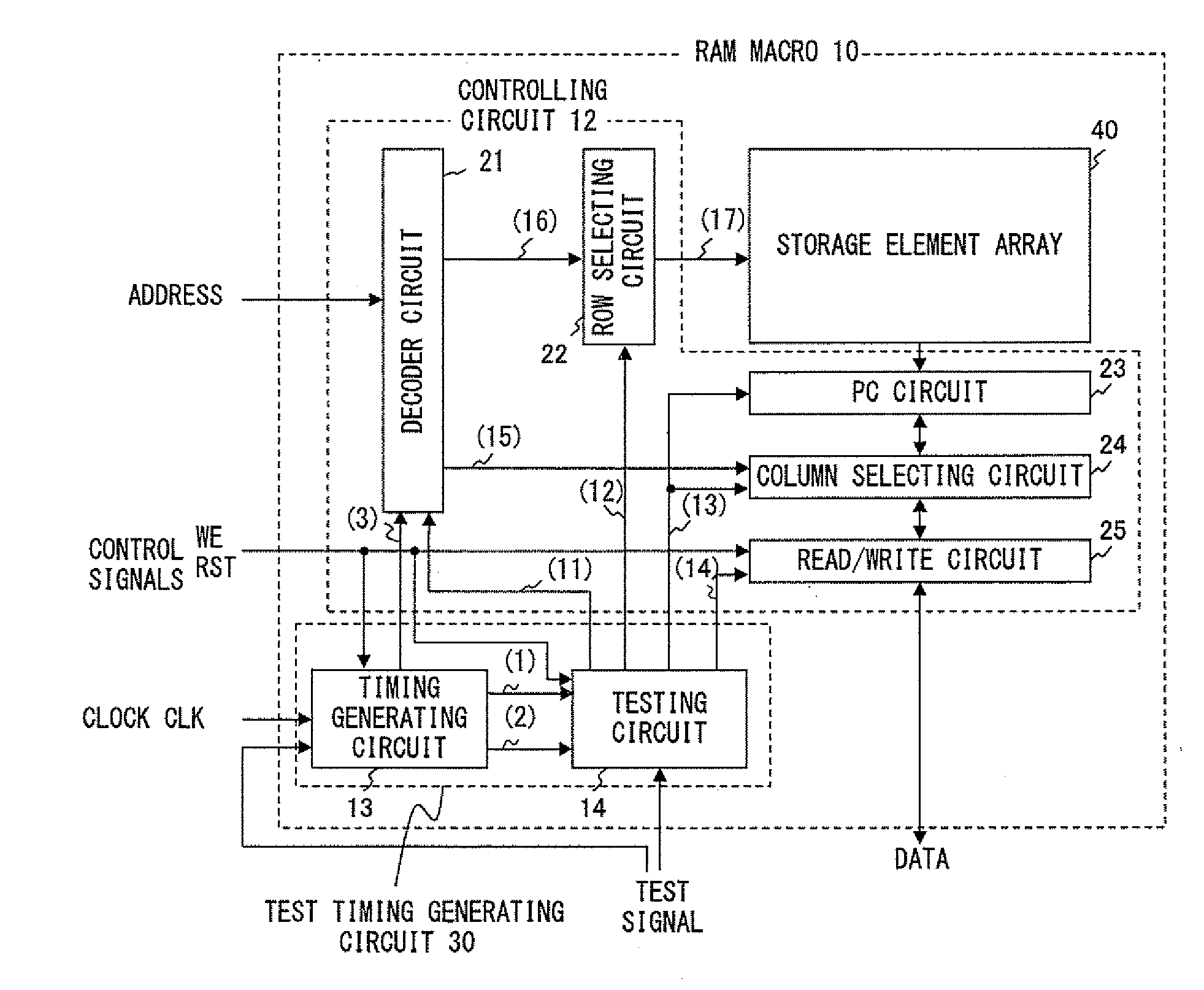
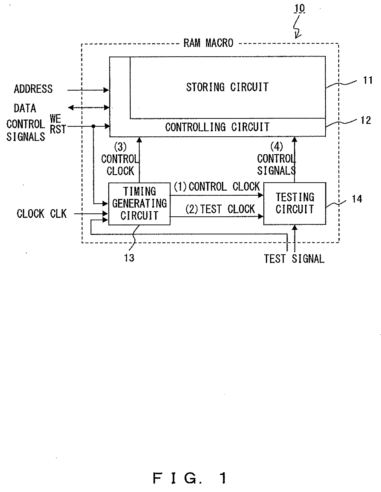
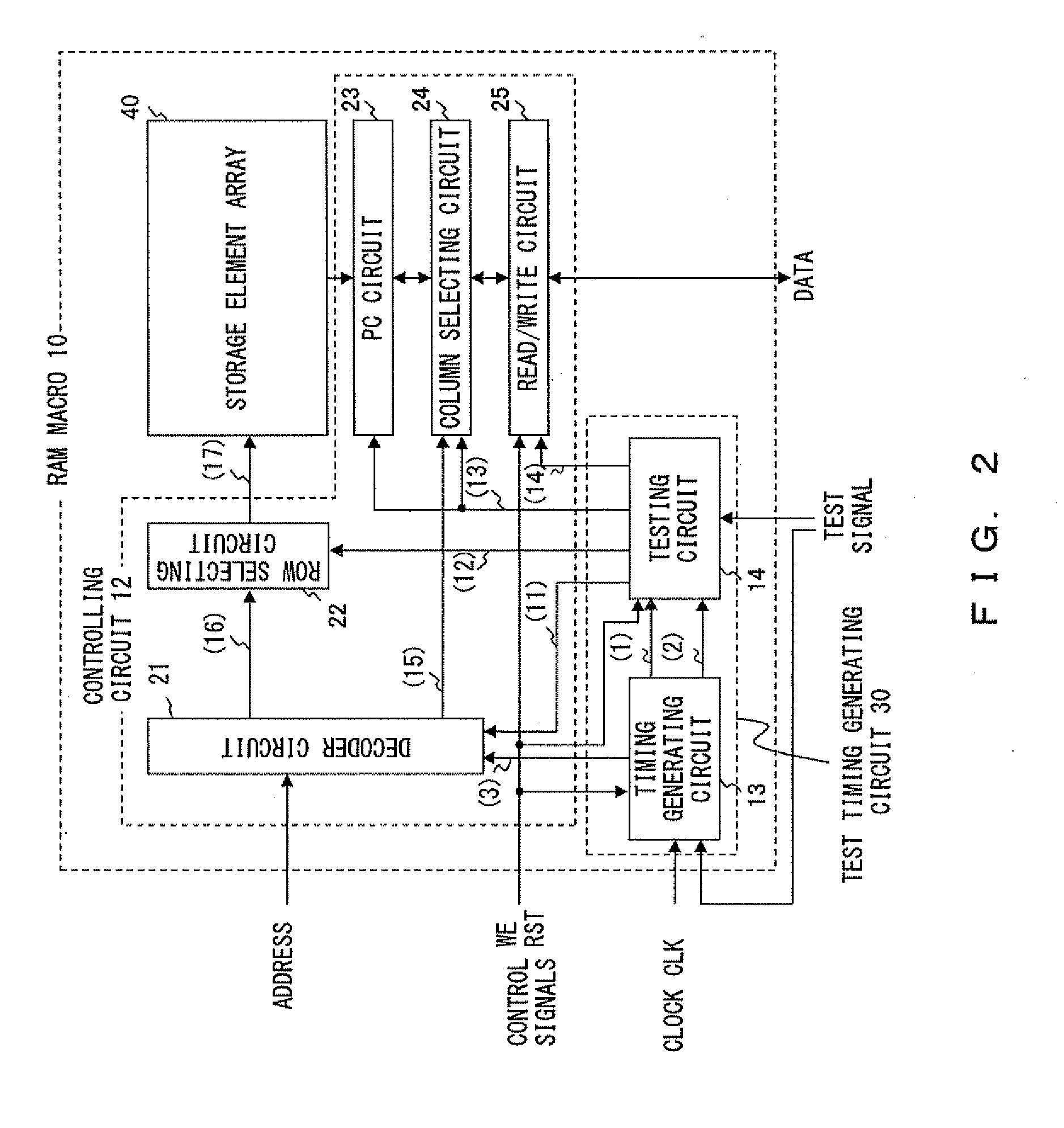
[0039]FIG. 1 shows the outline of the configuration of a RAM macro according to this preferred embodiment.

[0040]The RAM macro 10 shown in this figure comprises a storing circuit 11 composed of storage elements, a controlling circuit 12 for controlling the storing circuit 11, a timing generating circuit 13 for generating a timing based on an externally input clock CLK, and a testing circuit 14 for testing the storing circuit 11. A RAM of the RAM macro 10 according to this preferred embodiment is fundamentally an SRAM. However, the RAM may be a DRAM. However, in the case of the DRAM, a cell test period cannot be adjusted although write and read periods to be described later can be adjusted.

[0041]The timing generating circuit 13 generates a control clock (1) and a test clock (2) based on an externally input clock CLK, and outputs the generated clocks to the testing circuit ...


PUM


Abstract

A timing generating circuit generates a control clock (1) and a test clock (2) based on an externally input clock CLK, and outputs the generated clocks to a testing circuit. The control clock (1) is a signal the phase of which is delayed by a predetermined amount with reference to the clock CLK. This predetermined amount can be set/changed with an external test signal. The test clock (2) is nearly an inversion signal of the clock CLK. The testing circuit generates various types of control signals (4) based on either of the clocks (1) and (2), and distributes the signals to a controlling circuit. Which of the clocks (1) and (2) is selected in the testing circuit can be set with an external test signal.

Description

CROSS REFERENCE TO RELATED APPLICATION[0001]This application is a continuation of PCT application of PCT / JP2006 / 303656, which was filed on Feb. 28, 2006.BACKGROUND OF THE INVENTION[0002]1. Field of the Invention[0003]The present invention relates to a timing generating circuit included in a RAM macro, and a RAM macro including the timing generating circuit.[0004]2. Description of the Related Art[0005]Conventionally, there are testing circuits for testing a RAM macro as disclosed, for example, by Patent Documents 1, 2, etc.[0006]According to the invention disclosed by Patent Document 1, a fault of a memory cell is determined by causing access operations to be performed within a RAM at high speed with the use of an n-multiple (n is a real number) clock signal, which is generated by multiplying an externally input clock signal by n within a chip, as a clock signal for synchronizing operations within the RAM, and by making a comparison with an expected value only once at the end of one ...

Claims


Application Information

Patent Timeline
Patent Type & Authority Applications(United States)
IPC IPC(8): G11C8/18
CPCG11C11/41G11C29/14G11C29/12015
Inventor IJITSU, KENJI
Owner FUJITSU LTD
Why Eureka
Try Eureka