Re-entrant structure for thin disk resonators

a resonator and thin disk technology, applied in the direction of optical resonator shape and construction, laser details, active medium shape and construction, etc., can solve the problems of reducing the saturated gain level of the resonator, and reducing the resonator's resonator's resonator's resonator, so as to reduce the buildup of wavefront errors and reduce the saturated gain level

Active Publication Date: 2009-03-05
THE BOEING CO
View PDF8 Cites 13 Cited by
  • Summary
  • Abstract
  • Description
  • Claims
  • Application Information

AI Technical Summary

Benefits of technology

[0009]The present embodiment addresses such a need as it comprises a multipass architecture which enables a low saturated gain level to be achieved, while using structural symmetries to cancel disk aberrations and reduce wavefront error buildup.

Problems solved by technology

Although the thin disk's geometry is thermally advantageous, thin disk lasers are generally limited in pump diameter due to the onset of lateral lasing parasitics.
Such a resonator, however, typically fails to achieve high power with high beam quality.
Furthermore, resonators that support high beam quality typically introduce an optical loss for higher order modes either through aperturing, absorption or increased output coupling by round-trip magnification of the lasing mode (e.g., as in unstable resonators).
As a result of each of these aspects, an undesirable increase in threshold gain occurs.
This is understood as prior attempts in adding thickness to the individual thin-disks degraded efficiency and thermo-optical performance.
Unfortunately, both techniques necessitate an increase in the number of optical elements used in the resonator, and hence the total round-trip wavefront error which scales with the number of optical surfaces encountered, and generally degrades the beam quality of the laser.
It is understood that marginally stable resonators and low magnification unstable resonators will not accommodate large wavefront errors and are relatively more sensitive to alignment errors.
However, active mirror approaches not only typically require many degrees of freedom to properly correct a disk-laser system, but must include magnification / demagnification elements (MDEs).
Similarly, nonlinear elements, while potentially useful, currently exhibit losses too great to be efficient used intra-cavity.

Method used


Image

  • Re-entrant structure for thin disk resonators
  • Re-entrant structure for thin disk resonators
  • Re-entrant structure for thin disk resonators

Examples


Embodiment Construction

[0028]The following description is presented to enable one of ordinary skill in the art to make and use the embodiment and is provided in the context of a patent application and its requirements. Various modifications to the implementations and the generic principles and features described herein will be readily apparent to those skilled in the art. Thus, the present embodiment is not intended to be limited to the implementations shown, but is to be accorded the widest scope consistent with the principles and features described herein.

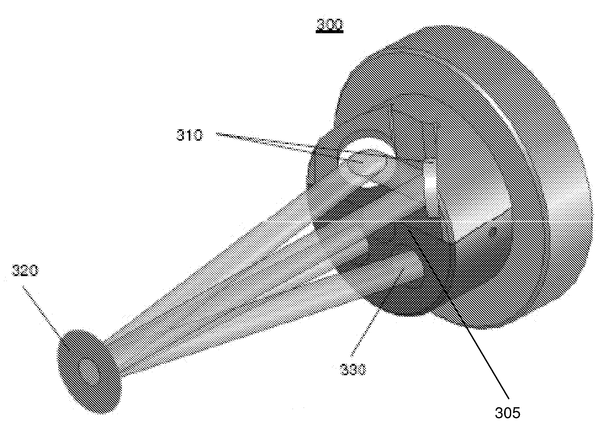
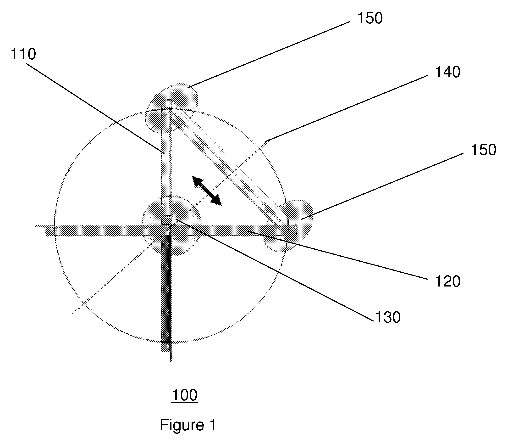
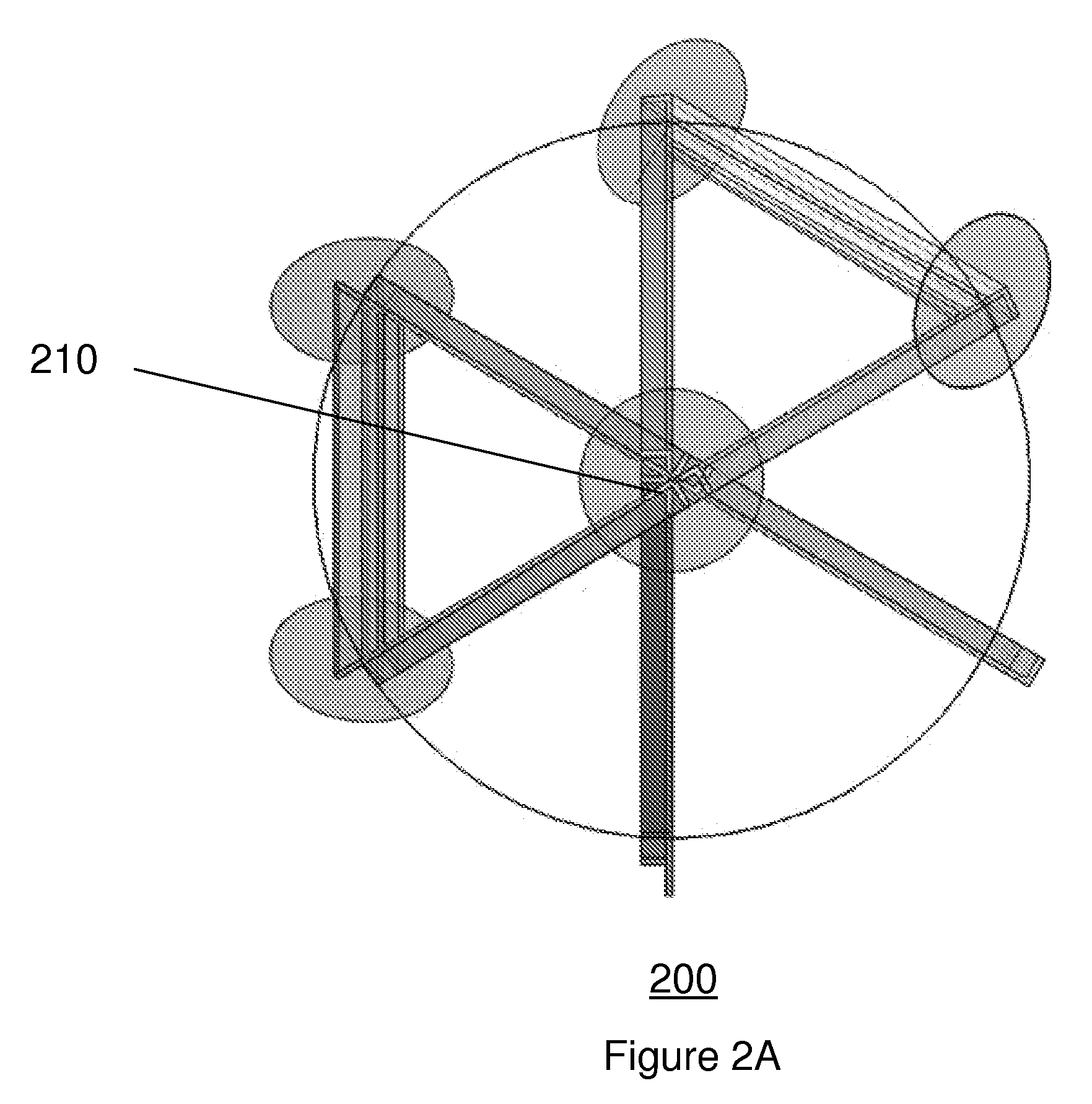
[0029]In one implementation of the present embodiment, an intra-cavity reflector assembly employing pairs of dielectric reflecting mirrors to multipass the gain generator of a thin-disk laser while making use of symmetry to reduce reflected wavefront error, and producing polarized laser output is provided. Additionally, in a further aspect, in an implementation of the present embodiment, the gain disk may be rotated so that the fold plane-of-symmetry r...


PUM


Abstract

The present embodiment provides a system and method for lowering the saturated gain level of a thin-disk laser oscillator by multipassing each gain generator in such a way to cancel some of the wavefront error contributions from the disk surfaces. Wavefront aberrations introduced on one pass of the gain disk are canceled through symmetry on successive passes. The reduced wavefront error significantly improves design space for single-mode resonators. Maximum effectiveness is achieved by rotating the gain disk so that the fold plane-of-symmetry reverses the largest wavefront error or specifically chosen functional forms.

Description

FIELD OF THE INVENTION[0001]The present embodiment relates generally to solid-state lasers, and more particularly, to an intra-cavity reflector assembly having a plurality of dielectric reflecting mirrors.BACKGROUND OF THE INVENTION[0002]Solid-state lasers employing a thin disk of lasing material have been demonstrated at power levels of a few kW in multimode optical beams. A thin disk laser is recognized to be a unique kind of diode-pumped, high power solid-state laser, differing from conventional rod or slab lasers in its gain medium geometry. The thin (˜100 μm) disk dimension of the active medium enables large optical pumping densities, efficient extraction, and importantly, minimal thermo-optical distortion of optical beams in the crystal. The geometry of the thin disk provides a large ratio of cooling surface to heat-producing volume, while providing a nearly one-dimensional heat flow that is collinear to the lasing beam axis. The latter minimizes thermal lensing and allows ope...

Claims


Application Information

Patent Timeline
Patent Type & Authority Applications(United States)
IPC IPC(8): H01S3/081
CPCH01S3/025H01S3/027H01S3/0604H01S3/07H01S3/1026H01S3/0804H01S3/0813H01S3/10061H01S3/08
Inventor BOSSERT, DAVID J.ROSSBACH, DENNIS R.
Owner THE BOEING CO
Why Eureka
Try Eureka