Bend insensitivity in single mode optical fibers

a single-mode optical fiber and insensitivity technology, applied in the field of single-mode optical fibers, can solve the problems of inability to bend access fibers, inability to meet the fundamental transverse mode of a standard smf, and inability to meet the fundamental transverse mode of a standard smf, and achieve the effect of improving mode discrimination

Active Publication Date: 2009-03-05
FURAKAWA ELECTRIC NORTH AMERICA INC
View PDF6 Cites 94 Cited by
  • Summary
  • Abstract
  • Description
  • Claims
  • Application Information

AI Technical Summary

Benefits of technology

[0019]FIG. 1G is a schematic, cross-sectional view of an optical fiber in accordance with another embodiment of our invention including

Problems solved by technology

In addition, however, some access fiber may have to be bent, for example, around the corners of walls and in wiring conduits or ducts.
When fiber is bent so severely, however, optical loss may increase to unacceptable levels.
In particular, the optical loss experienced by the fundamental transverse mode of a standard SMF, which may be within system specifications when t

Method used


Image

  • Bend insensitivity in single mode optical fibers
  • Bend insensitivity in single mode optical fibers
  • Bend insensitivity in single mode optical fibers

Examples


example i

[0075]In this example, the fiber preform had a diameter of 18.8 mm, and the drawn fibers had an outside diameter (OD) of either 119 μm or 125 μm. The various radial components had thickness / radius and index contrast (Δn) relative to the outer cladding region as listed below in Table I for the fiber having a 125 μm OD:

TABLE 1FIBER REGIONTHICKNESS (μm)RADIUS (μm)ΔnInner core4.90.005Shelf2.9−0.004Inner trench4.3−0.008Pedestal3.213.70.004Outer trench6.8−0.008Outer cladding220.000

[0076]The two fibers were characterized in terms of their cutoff wavelengths, bend loss (at a bend radius of 5 mm and at a wavelength of 1650 nm), and MFD (at a wavelength of 1550 nm), as indicated below in Table 2:

TABLE 2FIBER OD (μm)CUTOFF (nm)BEND LOSS (dB / m)MFD (μm)11914458.812515059.2

[0077]The 125-μm-OD fiber showed no impairment on preliminary CATV tests, despite the relatively high cutoff(1505 nm cutoff wavelength; 1553 nm signal wavelength).

[0078]The condition rbend>rcrit given by inequality (10) in this...

example ii

[0080]In this example, the fiber preform had a diameter of 19 mm, and the drawn fiber had an outside diameter (OD) of 125 μm. The various radial components had thickness / radius and index contrast (Δn) relative to the outer cladding region as listed below in Table 3:

TABLE 3FIBER REGIONTHICKNESS (μm)RADIUS (μm)ΔnInner core4.20.004Shelf1.6−0.001Inner trench5.7−0.005Pedestal2.312.70.003Outer trench7.1−0.005Outer cladding210.000

[0081]The fiber was characterized in terms of its cutoff wavelength, bend loss of 1 dB / m (at a bend radius of 6.25 mm and wavelength of 1550 nm), and MFD of 8.6 μm and 9.2 μm (at wavelengths 1310 nm and 1550 nm, respectively), as follows:

[0082]This fiber had a significantly lower cutoff of 1304 nm determined by ITU-2m measurement than either fiber of Example I. Some customers currently require a larger MFD and / or a cutoff<1260 nm, which can be attained by sacrificing bend loss. Example III below addresses such a fiber design.

[0083]At 1320 nm the fiber compares fav...

examples iii

, IV, V

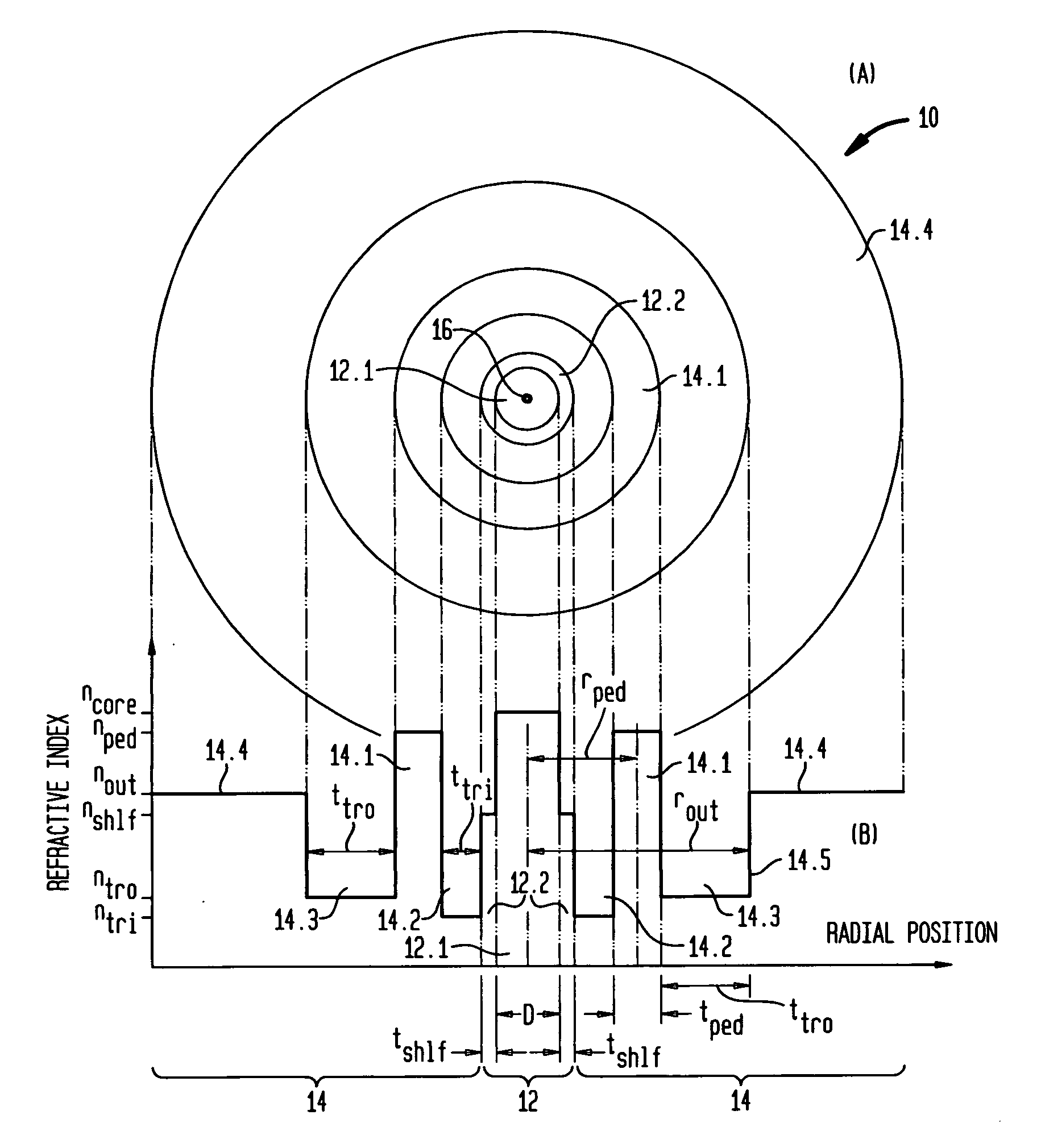
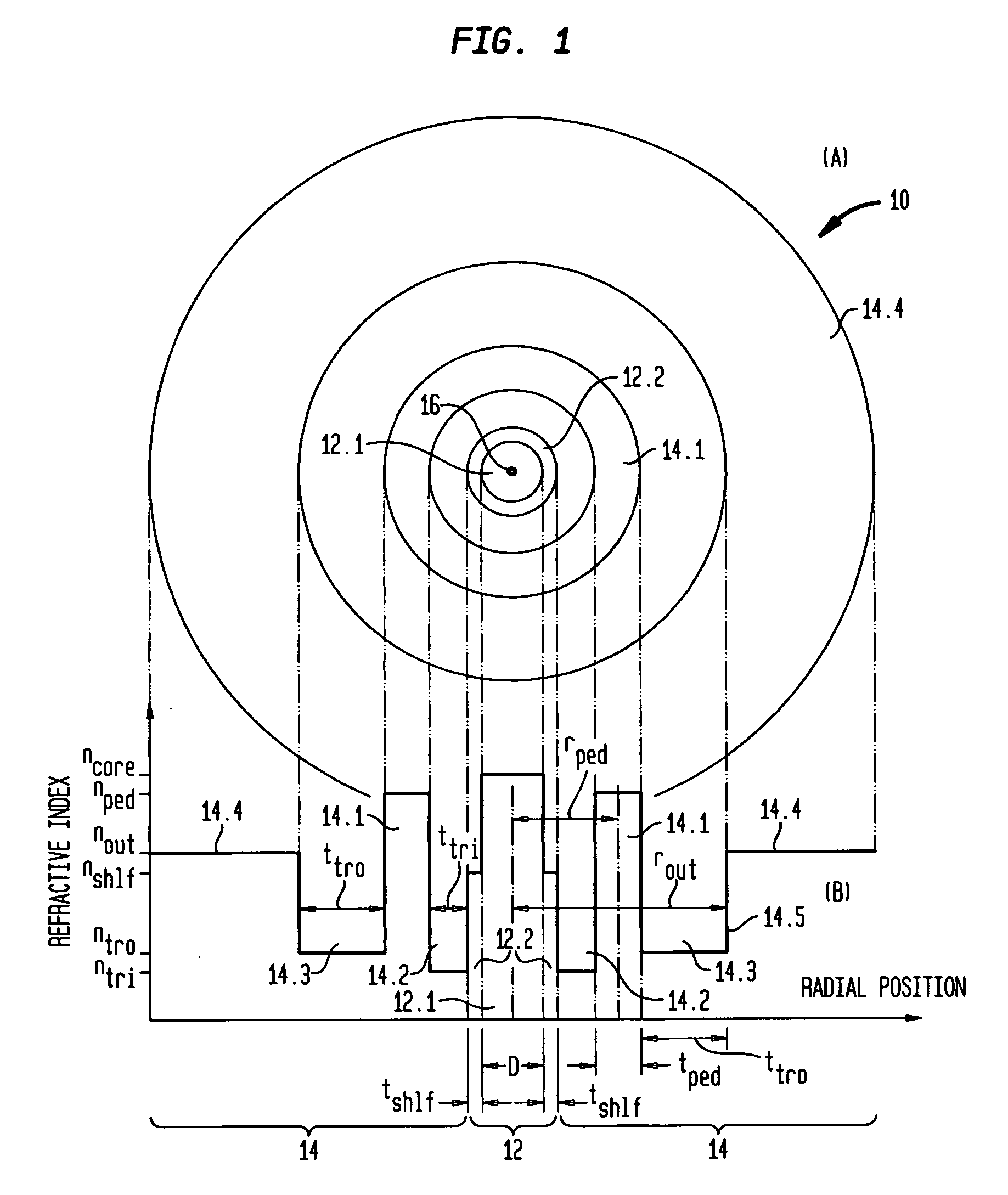
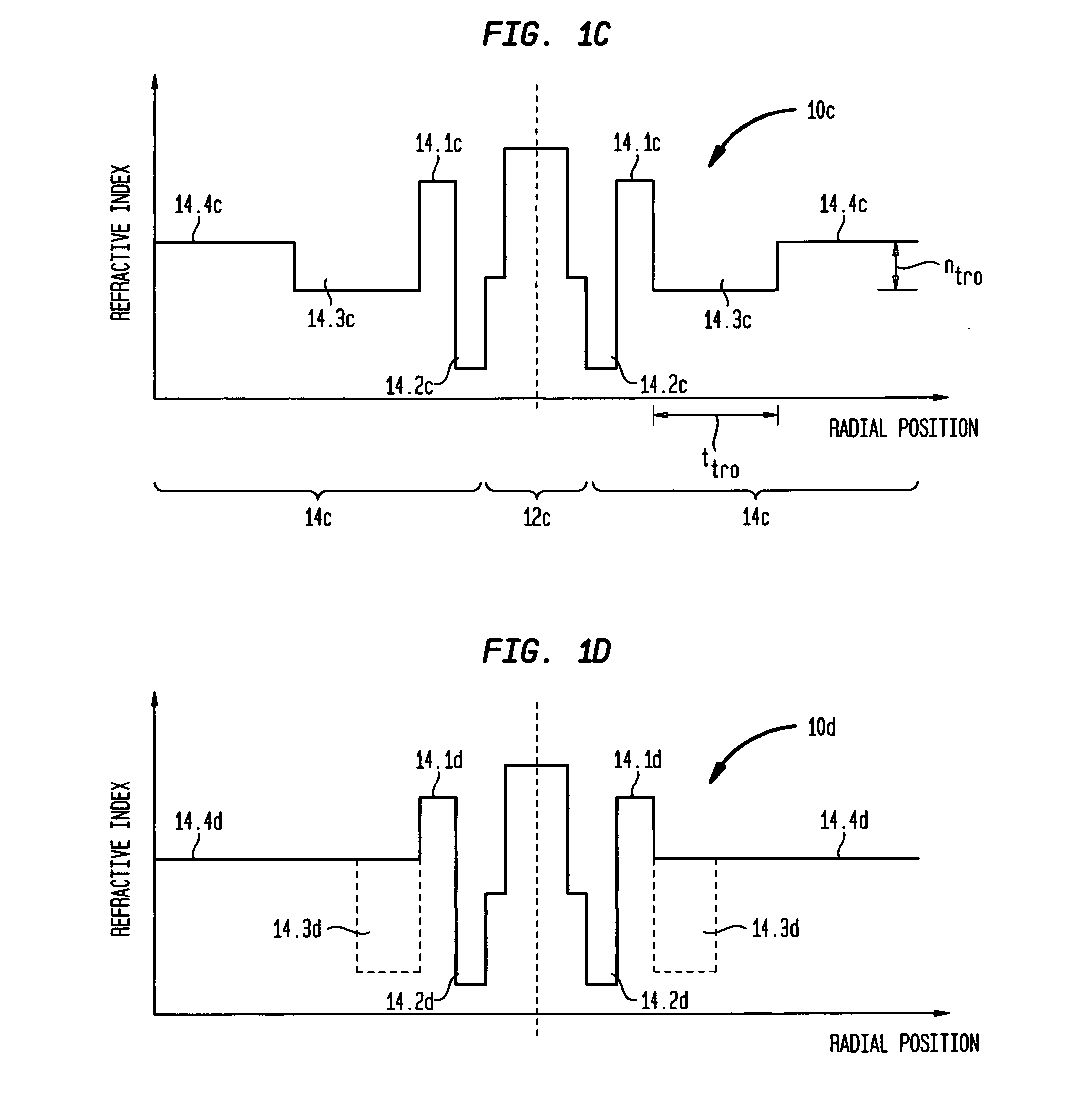
[0087]This set of examples illustrates several different embodiments of our invention: Example III—a fiber having a dual-trench, ring design (akin to FIG. 1B) in which the inner and outer trench regions are both relatively deep and have essentially the same index depth; Example IV—a very high performance fiber having a dual-trench, ring design (akin to FIG. 1B) in which the inner and outer trench regions are both relatively deep but the inner trench region is deeper than the outer trench region; and Example V—a fiber having a dual trench, ring design (akin to FIG. 1C) in which the outer trench region is much shallower than the inner trench region. Examples III-V are defined more specifically by the index profile parameters shown in Table 4 below:

TABLE 4Ex.rcoreΔncoretshelfΔnshlfttriΔntritpedΔnpedttroΔntrorpedIII4.40.00392.2−0.00044.7−0.00572.60.00397.2−0.005712.6IV4.50.00412.3−0.00104.0−0.00973.00.00368.6−0.006012.3V4.60.00421.90.00009.2−0.00601.70.005112.1−0.000816.5

Fibers b...


PUM


Abstract

An optical fiber that is relatively insensitive to bend loss comprises a core region and a cladding region configured to support and guide the propagation of light in a fundamental transverse mode, the cladding region including (i) an outer cladding region having a refractive index less than that of the core region, (ii) an annular cladding pedestal region having a refractive index higher than that of the outer cladding region and comparable to that of the core region, and (iii) an annular cladding inner trench region disposed between the core region and the pedestal region, the inner trench region having a refractive index less than that of the outer cladding region. In one embodiment, the fiber also includes a (iv) an annular cladding outer trench region disposed between the pedestal region and the outer cladding region, the outer trench region having a refractive index less than that of the outer cladding region. In addition, to suppress HOMs the pedestal region is configured to resonantly couple at least one other transverse mode of the core region to at least one transverse mode of the pedestal region. Such fiber is advantageously used as access fiber, but may have other applications, such as sensor fiber.

Description

CROSS-REFERENCE TO RELATED APPLICATIONS[0001]This application is a continuation-in-part of copending application Ser. No. 11 / 818,780 (Fini 5), which was filed on Jun. 15, 2007 and is entitled “Bend-Insensitivity in Single Mode Optical Fibers.” This application also claims priority from provisional application Ser. No. 60 / 030,713, which was filed on Feb. 22, 2008 and is entitled “Solid Ring-Assisted Fibers with Low Bend Loss.”BACKGROUND OF THE INVENTION[0002]1. Field of the Invention[0003]This invention relates to single mode optical fibers and, more particularly, to reducing bend sensitivity in such fibers. It also relates to fiber designs that are not only relatively bend insensitive but also effectively mode-matched to standard single mode fiber and / or have effectively cut off higher order transverse modes.[0004]2. Discussion of the Related Art[0005]In contrast with standard single mode optical fiber used, for example, in land line, undersea and metro systems, access fiber, which ...

Claims


Application Information

Patent Timeline
IPC IPC(8): G02B6/036
CPCG02B6/02366G02B6/02371G02B6/03688G02B6/03672G02B6/0238G02B6/02342
Inventor FINI, JOHN MICHAELKRISTENSEN, POUL
Owner FURAKAWA ELECTRIC NORTH AMERICA INC
Why Eureka
Try Eureka