Optical fiber with distributed bend compensated filtering

a technology of optical fiber and filtering, applied in the field of optical fibers with distributed bend compensation, can solve the problems of reducing the degree of filtering required, affecting the performance of optical fiber, etc., and achieves the effect of no loss and high loss

Active Publication Date: 2015-11-05
OFS FITEL LLC
View PDF0 Cites 47 Cited by
  • Summary
  • Abstract
  • Description
  • Claims
  • Application Information

AI Technical Summary

Benefits of technology

[0014]In one example, the cladding region comprises an inner cladding region and an outer cladding region and the optical fiber further comprises a trench region formed between the core region and the inner cladding region. The portion of cladding region having a graded index of refraction opposite the bend-induced gradient may extend over at least a portion of the inner cladding region. For a given mode of any fiber, the critical radius for bending is an important metric of filtering properties. By introducing a region having an index slope

Problems solved by technology

Light generated by SRS can act as noise in some systems, but can also lead to damage of optical components and system failure, particularly in high-power systems.
In large mode area filter fibers, there is typically a tradeoff between degree of filtering, effective area, and bend loss, e.g., a required degree of filtering becomes more difficult to achieve as mode area increases.
As mode area increases, it becomes more and more difficult to simultaneously achieve low signal loss (including macro-bend and micro-be

Method used


Image

  • Optical fiber with distributed bend compensated filtering
  • Optical fiber with distributed bend compensated filtering
  • Optical fiber with distributed bend compensated filtering

Examples


Embodiment Construction

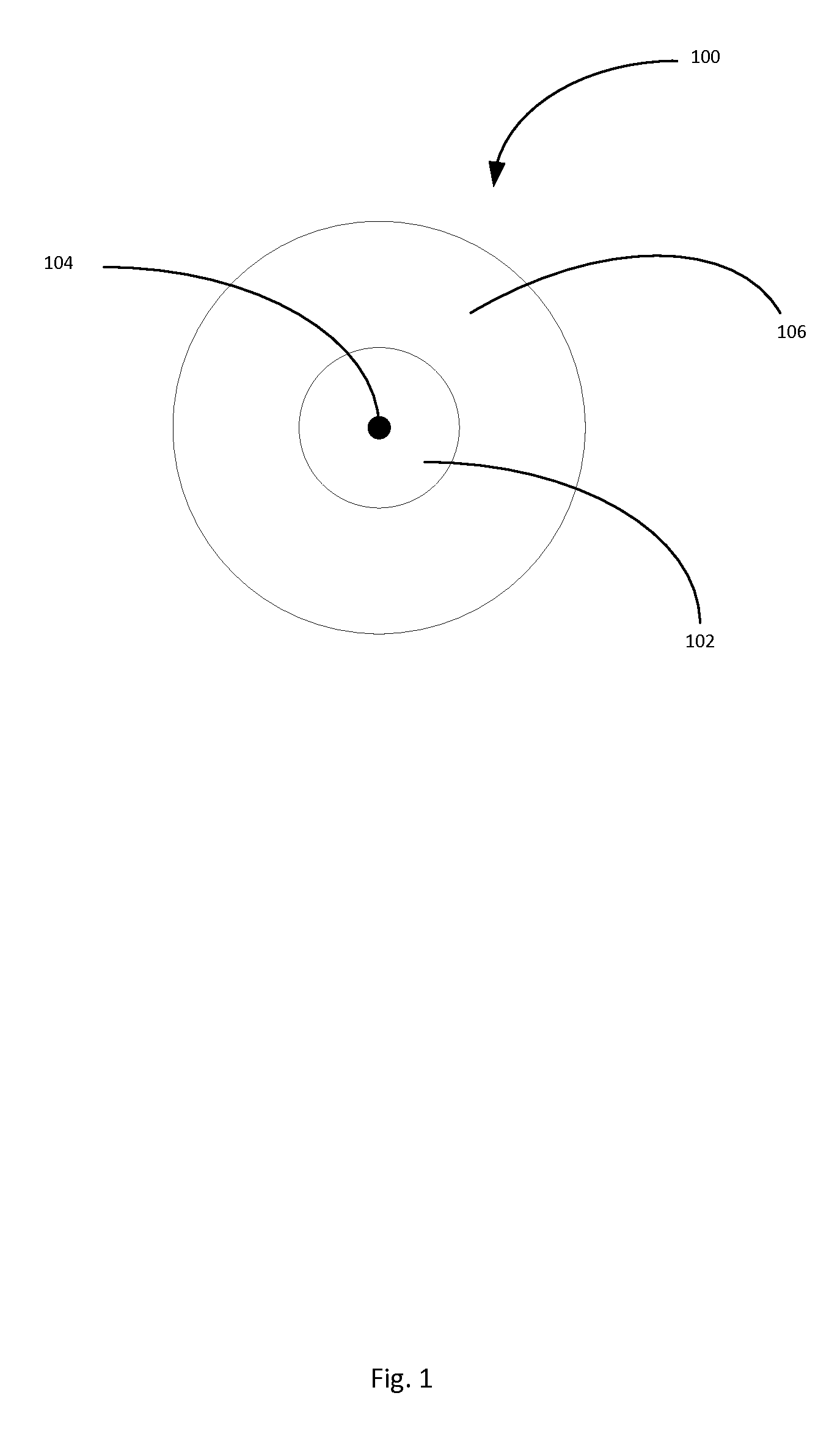
[0046]FIG. 1 is a schematic diagram of a core region 102 of a large mode area optical fiber 100. The fiber 100 may include the core region 102 having a longitudinal axis 104 and a cladding region 106 surrounding the core region. The core region 102 and cladding region 106 may be configured to support and guide the propagation of signal light in the core region 102 in the direction of the axis 104. To this end, the refractive index of the core region 102 (ncore=nc) is greater than that of the cladding region 106 (nclad). Preferably the core region 102 and the cladding region 106 are configured to propagate signal light preferentially in a fundamental transverse mode at the center wavelength of the signal light.

[0047]The term center wavelength of the signal light is intended to recognize the well-known phenomenon of line broadening; that is, no signal source emits light at precisely a single wavelength. Rather, all light sources emit at a center wavelength, where the intensity is typi...


PUM


Abstract

An optical fiber includes a core region having a longitudinal axis. At least a portion of the core region has a substantially helical shape about a helical axis. The longitudinal axis may be substantially tangential to a helical bend in the optical fiber. A cladding region surrounds the core region. The core region and cladding region may be configured to support and guide the propagation of signal light in a fundamental transverse mode in the core region in the direction of the longitudinal axis. The fiber has a bend-induced gradient in its equivalent index of refraction over the portion of the core region. The fiber has a bend-induced equivalent index of refraction. At least a portion of cladding region has a graded refractive index opposite that of the bend-induced gradient. The cladding region may be configured to have a substantially flat equivalent index in response to a helical bend of the optical fiber.

Description

CROSS-REFERENCE TO RELATED APPLICATIONS[0001]This application claims the benefit of U.S. provisional patent application No. 61 / 856,109 filed Jul. 19, 2013, the disclosure of which is incorporated herein by reference in its entirety. This application is a continuation-in-part and claims the benefit of international Patent Cooperation Treaty patent application No. PCT / US12 / 69814 filed Dec. 14, 2012, which claims the benefit of U.S. provisional patent application No. 61 / 570,389 filed Dec. 14, 2011 and U.S. provisional patent application No. 61 / 570,403 filed Dec. 14, 2011, the disclosures of which are incorporated herein by reference in their entirety.BACKGROUND OF THE INVENTION[0002]1. Field of the Invention[0003]The invention relates generally to optical fibers. More specifically, the invention relates to a large mode area fiber that is formed in the shape of a helix to cause the optical fiber to exhibit a refractive index profile that minimizes bend-induced limitations on the fiber's...

Claims


Application Information

Patent Timeline
IPC IPC(8): G02B6/028G02B6/036G02B6/02
CPCG02B6/0288G02B6/03627G02B6/02009G02B6/02323G02B6/0283G02B6/03644G02B6/03666G02B6/028G02B6/0365G02B6/03655
Inventor FINI, JOHN M.NICHOLSON, JEFFREY W.
Owner OFS FITEL LLC
Why Eureka
Try Eureka