Protection cover attachment structure of battery-mounted fusible link unit

Inactive Publication Date: 2009-03-05
YAZAKI CORP
View PDF8 Cites 24 Cited by
  • Summary
  • Abstract
  • Description
  • Claims
  • Application Information

AI Technical Summary

Benefits of technology

[0015]According to the present invention, when the protection cover is simply put over the resin housing, the both side edges of the side surface cover of the protection cover are inserted into the slide guide grooves to be guided. Therefore, the protection cover can be reliably positioned and easily attached to a predetermined position, thus improving the workability in attaching the protection cover. The upper surface cover covers the first and/or second terminal sections in the upper surface of the fusible link unit and the entire part connected to the battery post. The side surface covers cover the wire-attached terminals exposed in the side surfa

Problems solved by technology

In the case of attaching the protection cover to the fusible link unit using a hinge like the technique described in Japanese Patent Laid-open Publication No. 10-338085, a part of a constituent component of the hinge needs to be provided for a housing of the fusible link unit, and the structure thereof is complicated.
Moreover, the fusible link unit and protection cover need to be linked by the hinge in advance, and the assembly thereof is troub

Method used


Image

  • Protection cover attachment structure of battery-mounted fusible link unit
  • Protection cover attachment structure of battery-mounted fusible link unit
  • Protection cover attachment structure of battery-mounted fusible link unit

Examples


Example

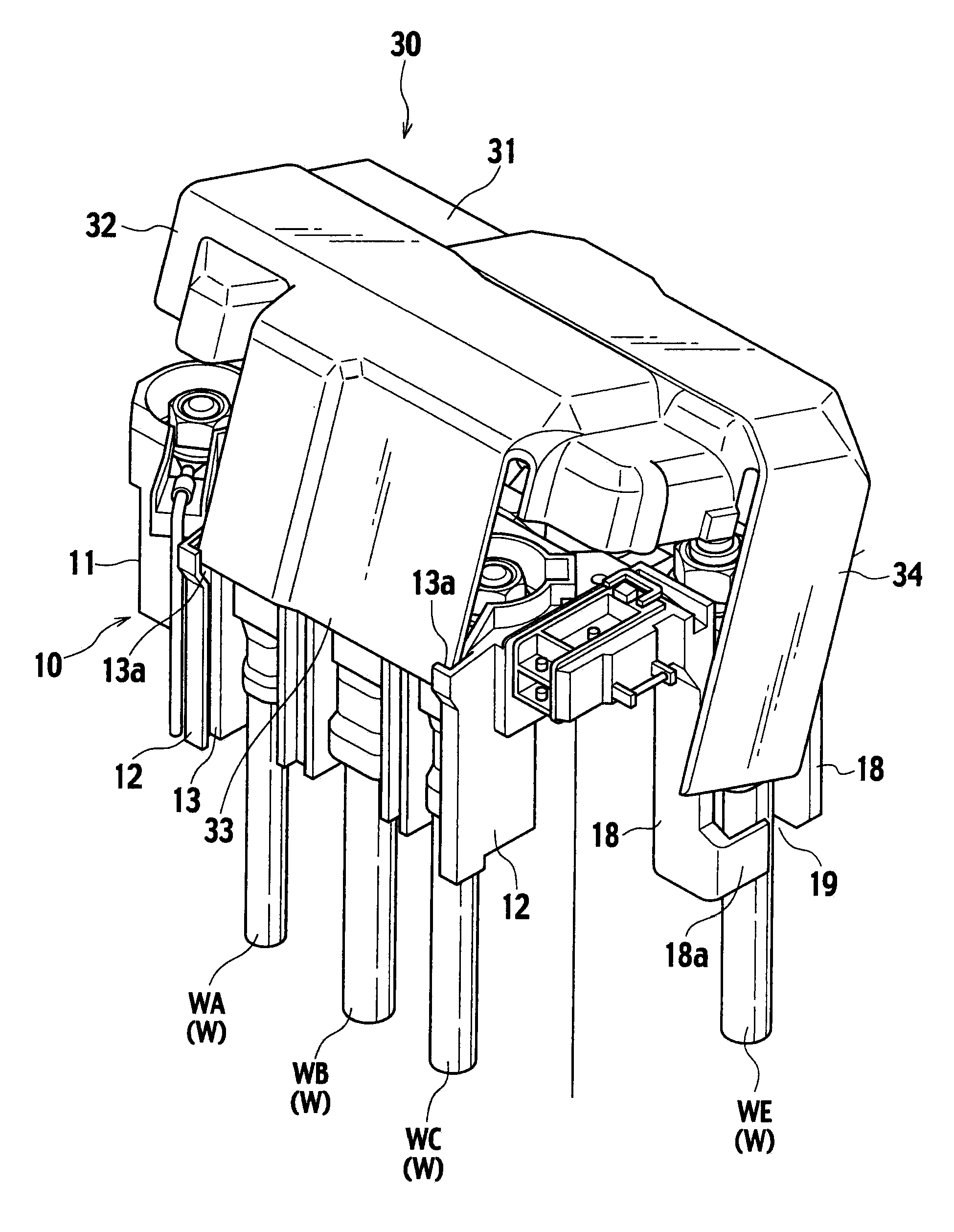
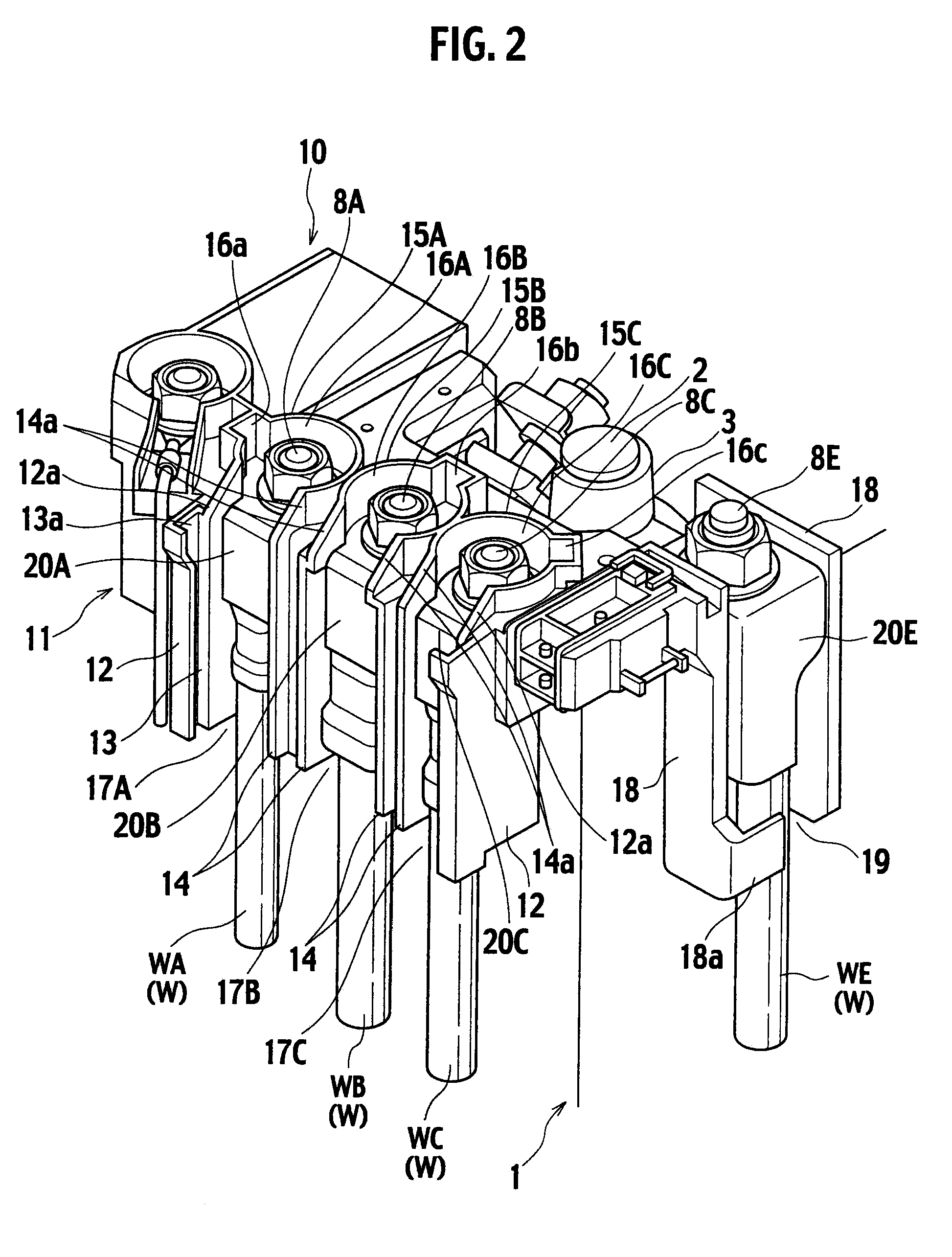
[0021]Hereinafter, a description is given of an embodiment of the present invention with reference to the drawings. As shown in FIGS. 2 and 3, a structure according to the embodiment includes a fusible link unit 10 and a protection cover 30. The fusible link unit 10 includes a first terminal section BE and second terminal sections 8A to 8C, which are provided on an upper surface of the fusible link unit 10. The first terminal section 8E and second terminal sections BA to BC are connected to wire-attached terminals 20A to 20C provided with wires W (WE, WA, WB, and WC) extending downward, respectively. The protection cover 30 is put over the fusible link unit 10 which is directly mounted on the battery 1.

[0022]Herein, the first terminal section 8E is an input terminal section connected to the battery post 2 through the battery terminal 3 and serves as a second terminal section connected to a starter wire WE-attached terminal 20E. The other second terminal sections BA to BC are output ...


PUM


Abstract

A protection cover attachment structure of a battery-mounted fusible link unit includes a fusible link unit including a resin housing with a slide guide groove and a protection cover including an upper surface cover and side surface covers. The upper surface cover covers the upper surface of the resin housing and a battery post and a battery terminal. The side surface covers extend downward from a peripheral edge of the upper surface cover and cover the wire-attached terminals connected to the terminal sections of the fusible link unit and upper part of wires which are connected to the terminals and extended downward. When the protection cover is put over the resin housing, the slide guide grooves restricts the position of the protection cover and guides a side edge of at least one of the side surface covers downward.

Description

CROSS REFERENCE TO RELATED APPLICATION[0001]This application is based upon and claims the benefit of priority from Japanese Patent Application No. 2007-227438 filed on Sep. 3, 2007, the entire contents of which are incorporated herein by reference.BACKGROUND OF THE INVENTION[0002]1. Field of the Invention[0003]The present invention relates to an attachment structure of a protection cover of a fusible link unit (a battery fuse) directly mounted on a battery post.[0004]2. Description of the Related Art[0005]In the case where a fusible link unit for distributing power to loads is directly mounted on a battery of an automobile, at least a part of the fusible link unit directly connected to the battery post through a battery terminal is covered with a resin-made protection cover separately attached.[0006]Japanese Patent Laid-open Publication No. 10-338085 discloses a technique to attach a protection cover serving in such a manner as described above. In this technique, the protection cove...

Claims


Application Information

Patent Timeline
IPC IPC(8): H01M2/04H05K7/00H01M50/583H01M50/588H01M50/591
CPCB60R16/04H01M2/043Y02E60/12H01R11/287H01R13/447H01M2/34Y02E60/10H01M50/588H01M50/591H01M50/583
Inventor OHASHI, NORIHIROTSUKIJI, HIDEAKI
Owner YAZAKI CORP
Why Eureka
Try Eureka