Connector

a technology of connecting rods and contact rods, applied in the direction of coupling contact members, fixed connections, coupling device connections, etc., can solve the problems of poor connection between the pitch direction shield b>81/b> and the ground, and achieve the effect of enhancing the reliability of connection

Active Publication Date: 2009-03-05
MATSUSHITA ELECTRIC WORKS LTD
View PDF10 Cites 55 Cited by
  • Summary
  • Abstract
  • Description
  • Claims
  • Application Information

AI Technical Summary

Benefits of technology

[0012]It is an object of the present invention to provide a connector capable of enhancing the reliability of connection between the ground and a shield constituting a shell.

Problems solved by technology

However, since the pitch direction shield 81 is grounded through the terminal direction shield 82, the reliability of connection between the pitch direction shield 81 and the ground is poor.

Method used


Image

  • Connector
  • Connector
  • Connector

Examples


Embodiment Construction

[0057]Preferred embodiments of the present invention will be explained below with reference to FIGS. 2 to 16.

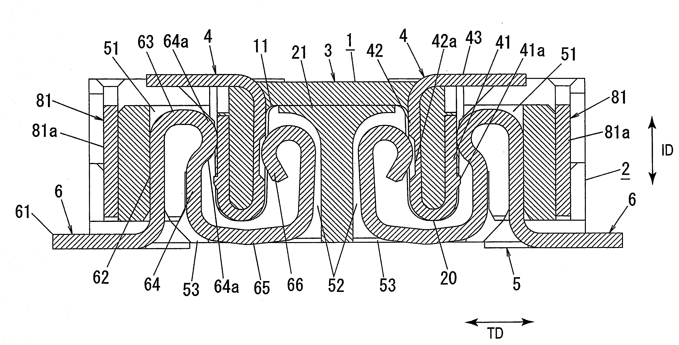
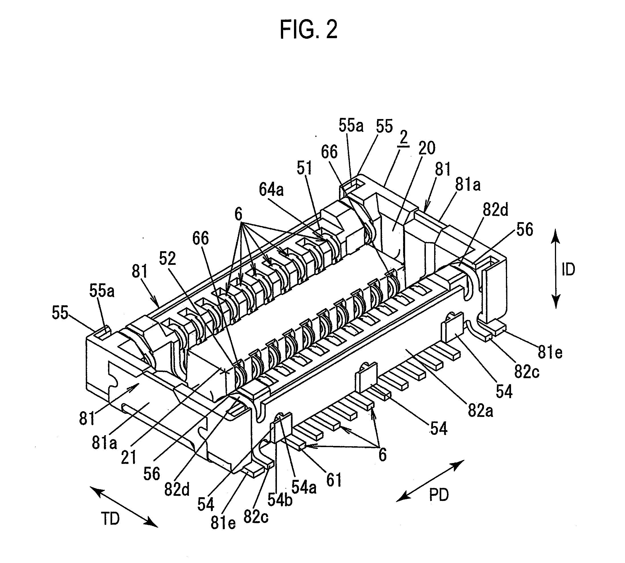
[0058]As shown in FIG. 3, a connector according to an embodiment of the invention includes a header 1 mounted on a first printed wiring board (not shown) and a socket 2 mounted on a second printed wiring board (not shown). The socket 2 includes a connection recess 20 into and from which the header 1 is inserted and pulled out. If the header 1 is inserted into the connection recess 20 in such a manner that the first printed wiring board and the second printed wiring board are opposed to each other, the first printed wiring board and the second printed wiring board are electrically connected to each other through the header 1 and the socket 2.

[0059]For convenience sake, the vertical direction and the lateral direction are defined based on FIG. 3. That is, a direction in which the header 1 is inserted into the connection recess 20 is called “downward”, and a direction in which t...


PUM


Abstract

To provide a connector that enhances the reliability of connection between the ground and a shield constituting a shell. A socket constitutes the connector together with a header which is mounted on a different printed wiring board. The socket includes a socket body which is provided with a connection recess, a plurality of socket contacts which are held by the socket body, and a pitch direction shield and a terminal direction shield constituting the shell which surround the connection recess and which prevents electromagnetic noise from coming in and out. The pitch direction shield and the terminal direction shield are provided with terminals soldered to conductive pattern of the ground.

Description

BACKGROUND OF THE INVENTION[0001]1. Field of the Invention[0002]The present invention relates to a connector.[0003]2. Description of the Related Art[0004]Conventionally, as a connector which electrically connects printed wiring boards to each other, there is a known connector including a header mounted on a first printed wiring board and a socket mounted on a second printed wiring board which is opposed to the first printed wiring board.[0005]As a connector of this kind, there is one having a socket 2 as shown in FIGS. 1A and 1B (for example, see Japanese Patent Application Laid-open No. 2006-59589).[0006]The socket 2 includes a socket body 5 which is made of insulation material and provided with a connection recess 20. A header is inserted into and pulled out from the connection recess 20 in a predetermined insertion / withdrawal direction ID (vertical direction in FIG. 1B). The socket 2 also includes a plurality of socket contacts 6 held by the socket body 5 such that the socket con...

Claims


Application Information

Patent Timeline
Patent Type & Authority Applications(United States)
IPC IPC(8): H01R12/00
CPCH01R12/57H01R12/52H01R13/20H01R12/51H01R13/6582
Inventor MIYAZAKI, YOJIOKURA, KENJI
Owner MATSUSHITA ELECTRIC WORKS LTD
Why Eureka
Try Eureka