Combustors with impingement cooled igniters and igniter tubes for improved cooling of igniters

a technology of igniters and igniter tubes, which is applied in the direction of efficient propulsion technologies, machines/engines, lighting and heating apparatus, etc., can solve the problems of reducing affecting the cooling efficiency of the igniter, and inducing potentially damaging thermal stresses into the combustor

Active Publication Date: 2009-03-12
HONEYWELL INT INC
View PDF24 Cites 39 Cited by
  • Summary
  • Abstract
  • Description
  • Claims
  • Application Information

AI Technical Summary

Benefits of technology

The present invention provides a combustor for a gas turbine engine with an improved fuel ignition system. The combustor includes an inner liner, an outer liner, a fuel igniter, and an igniter tube. The igniter tube has a plurality of channels that direct cooling air towards the tip of the fuel igniter to improve ignition efficiency. The igniter tube is designed to mount the fuel igniter to the outer liner and includes an igniter boss and a supporting ring with a plurality of holes to form the channels. The technical effects of this invention include improved ignition efficiency, reduced emissions, and improved engine performance.

Problems solved by technology

However, over time, continued operation may induce potentially damaging thermal stresses into the combustor that exceed an ultimate strength of materials used in fabricating the components of the combustor.
For example, thermally induced transient and steady state stresses may cause low cycle fatigue (LCF) failure of the igniter.
Cooling the igniter, particularly the tip portion of the igniter closest to the combustion process, presents challenges.
However, this arrangement is not very efficient because it requires a relatively large amount of cooling air to sufficiently cool the tip portion of the igniter.
The large amount of air required to effectively cool the tip portion of the igniter in this manner may adversely impact the combustion conditions within the combustion chamber.
Particularly, a large amount of cooling air may have a perturbative effect on the ignition process, gaseous emissions, and the temperature distribution of hot gases entering the turbine.
This can additionally reduce the effectiveness of the igniter for igniting the fuel and air mixture.
Moreover, excess cooling air can disrupt the liner cooling film and result in local hot spots immediately downstream of the igniter in the combustor liner.

Method used


Image

  • Combustors with impingement cooled igniters and igniter tubes for improved cooling of igniters
  • Combustors with impingement cooled igniters and igniter tubes for improved cooling of igniters
  • Combustors with impingement cooled igniters and igniter tubes for improved cooling of igniters

Examples


Embodiment Construction

[0012]The following detailed description of the invention is merely exemplary in nature and is not intended to limit the invention or the application and uses of the invention. Furthermore, there is no intention to be bound by any theory presented in the preceding background of the invention or the following detailed description of the invention.

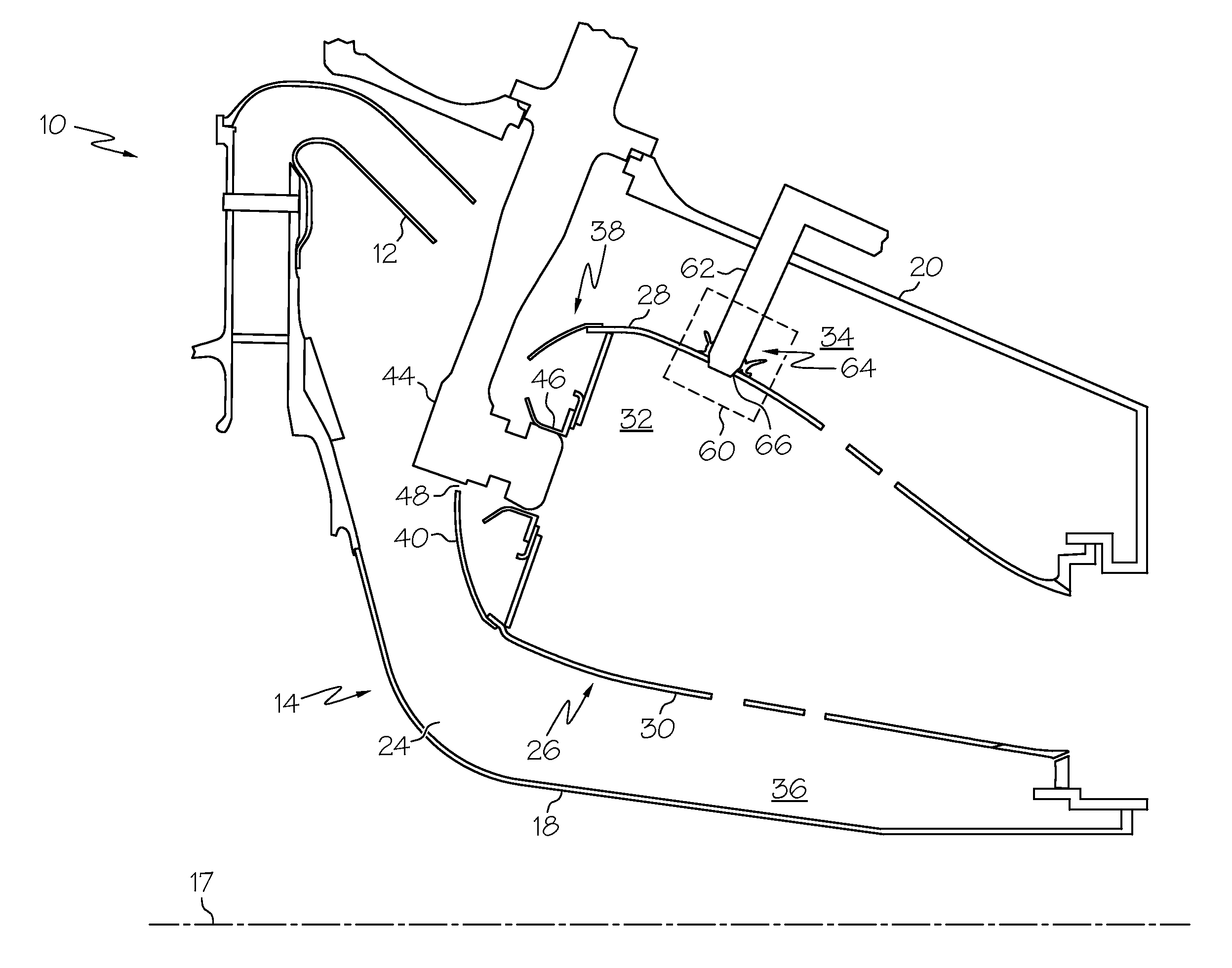
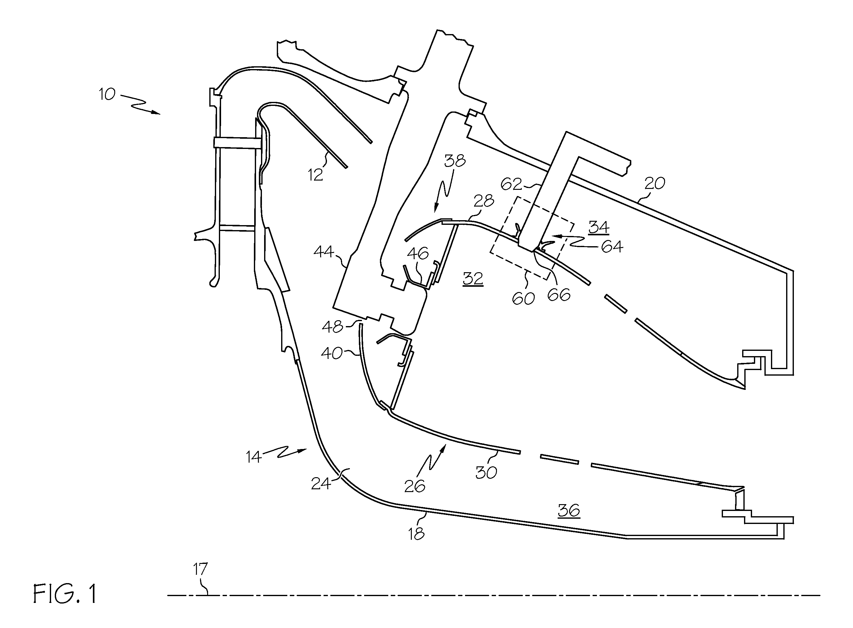
[0013]FIG. 1 is a cross-sectional view of a combustor 14 for a gas turbine engine in accordance with an exemplary embodiment of the present invention. Although the depicted combustor 14 is an annular combustor, any other type of combustor, such as a can combustor, can be provided. In an exemplary embodiment, the combustor 14 can form part of, for example, an auxiliary power unit for an aircraft or a propulsion system for an aircraft. The combustor 14 comprises an inner case 18 that extends annularly about a central axis 17 of the combustor 14 and an outer case 20 concentrically arranged with respect to the inner case 18. The inner and outer ...


PUM


Abstract

A combustor for a gas turbine engine is provided, and includes an inner liner; an outer liner circumscribing the inner liner and forming a combustion chamber with the inner liner; a fuel igniter comprising a tip portion configured to ignite an air and fuel mixture in the combustion chamber; and an igniter tube positioning the fuel igniter relative to the combustion chamber, the igniter tube having a plurality of channels configured to direct cooling air toward the tip portion of the fuel igniter.

Description

FIELD OF THE INVENTION[0001]The present invention generally relates to combustors for gas turbine engines, and more particularly relates to combustors with impingement cooled igniters and igniter tubes for improved cooling of igniters.BACKGROUND OF THE INVENTION[0002]Combustors are used to ignite and burn fuel and air mixtures in gas turbine engines. Known combustors include inner and outer liners that define an annular combustion chamber in which the fuel and air mixtures are combusted. The inner and outer liners are spaced radially inwardly from a combustor casing such that inner and outer passageways are defined between the respective inner and outer liners and the combustor casing. Fuel igniters extend through the combustor casing and the outer passageway, and are coupled to the outer liner by igniter tubes attached to the combustor liner. More specifically, the fuel igniter tubes secure and maintain the igniters in alignment relative to the combustion chamber as well as provide...

Claims


Application Information

Patent Timeline
Patent Type & Authority Applications(United States)
IPC IPC(8): F02C7/264F23R3/42
CPCF02C7/264F05D2260/201F23R3/002F23R3/04Y02T50/675F23R3/60F23R2900/00012F23R2900/03044F23R3/06Y02T50/60
Inventor ZUPANC, FRANK J.YANKOWICH, PAUL R.
Owner HONEYWELL INT INC
Why Eureka
Try Eureka