External Container for an Implant Carrier

Inactive Publication Date: 2009-03-12
STRAUMANN HLDG AG
View PDF3 Cites 26 Cited by
  • Summary
  • Abstract
  • Description
  • Claims
  • Application Information

AI Technical Summary

Benefits of technology

[0004]The object of the present invention is to overcome the above-mentioned disadvantages of known external containers for implant carriers an

Problems solved by technology

Due to the force acting continuously during screwing, the spring is worn out, losing its elasticity since it constantly remains in a tensioned state.
Therefore, the implant carrier can fall down from the lid when it is taken out or the lid is screwed off, since the retaining force would not

Method used


Image

  • External Container for an Implant Carrier
  • External Container for an Implant Carrier
  • External Container for an Implant Carrier

Examples


Embodiment Construction

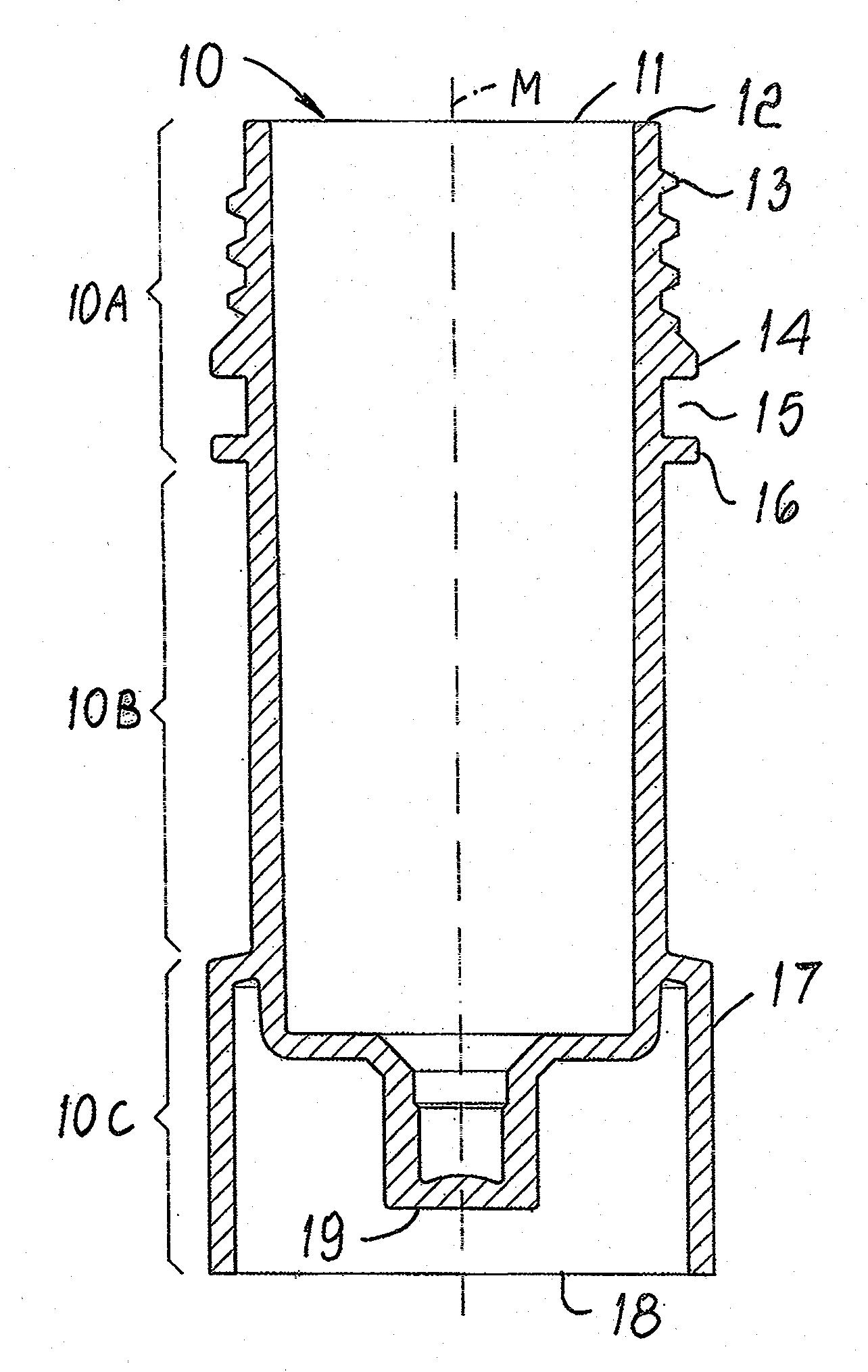
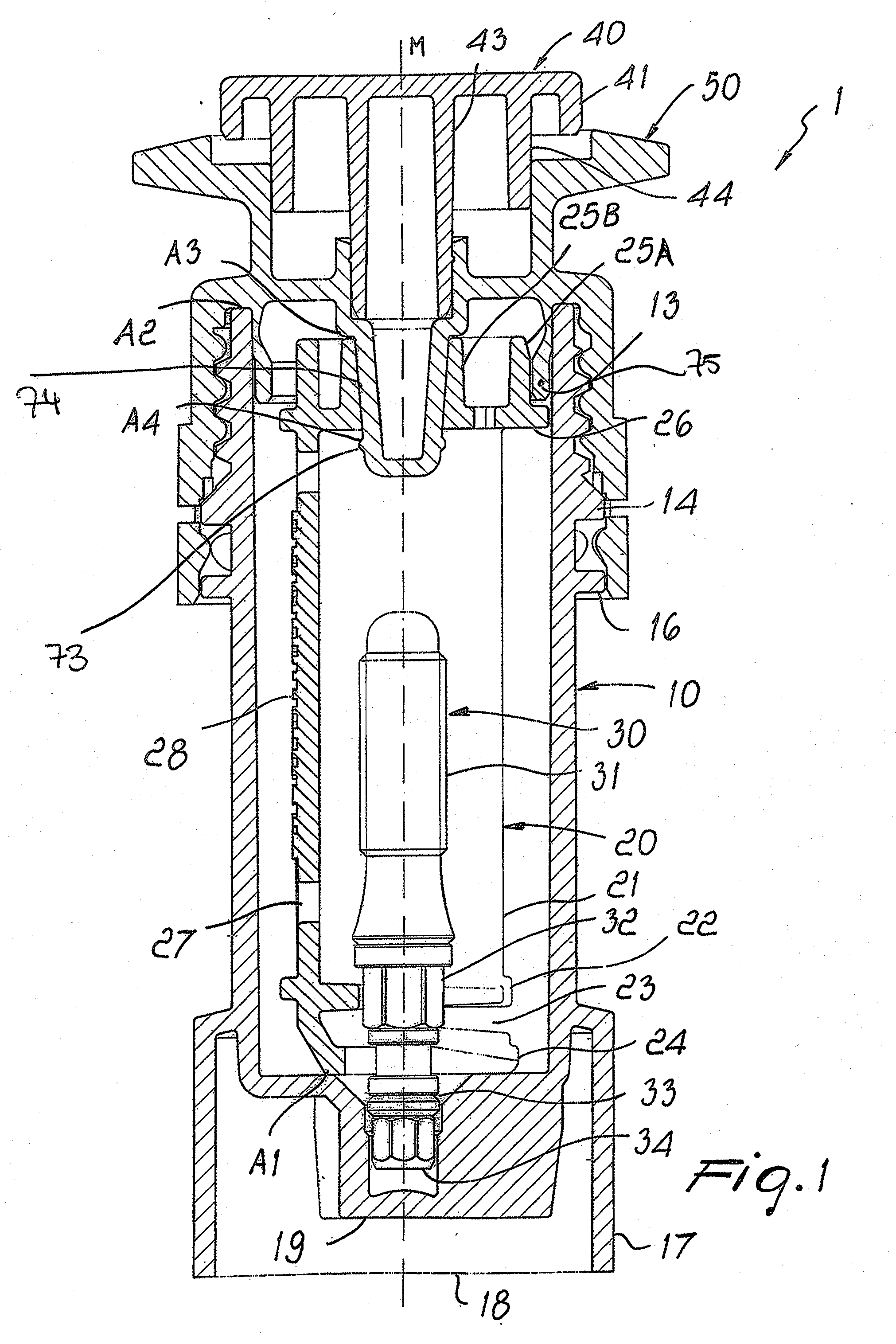
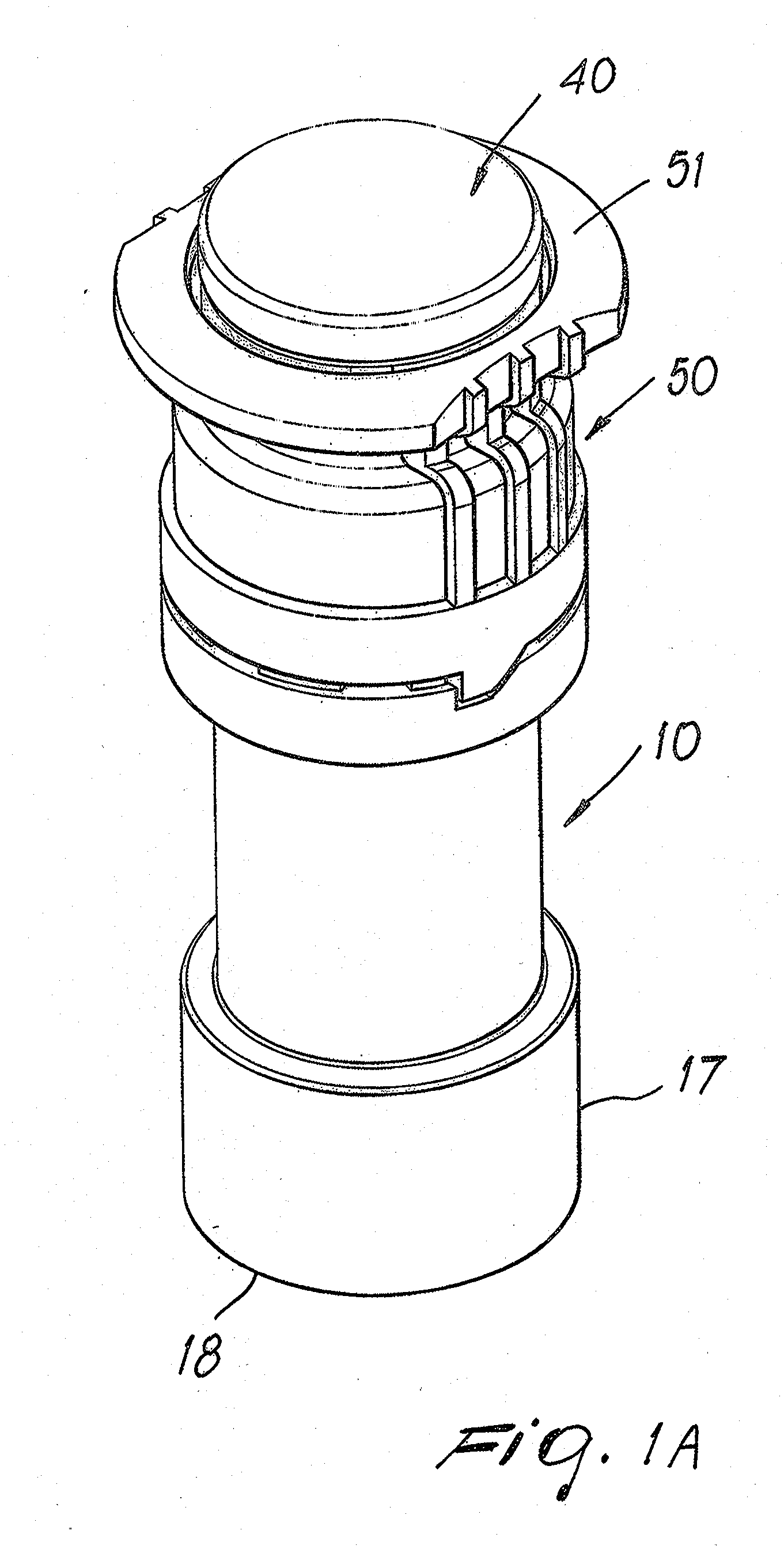
[0021]Based on the following FIGS. 1 through 3D, a currently preferred embodiment of the present invention of an external container 1 for an implant carrier 20 is described, consisting of a substantially cylindrical body portion 10 and a lid 50 which is screwed onto the cylindrical body portion 10.

[0022]FIG. 1 shows a longitudinal section of an external container 1 for an implant carrier 20 with a dental implant 30 fixed into place therein. The dental implant 30 is provided with a thread 31 (in the following second thread) to be screwed into the jaw of a patient, the dental implant 30 being screwed onto a holding element 32 and the part of the dental implant 30 which is to be implanted being enclosed within the implant carrier 20. The implant carrier 20 has a carrier shaft 21 in which the dental implant 30 is positioned. On one side, the carrier shaft 21 borders on a jaw-like portion 23 which is formed between a first plate 22 and a second plate 24 and is used to slide in the dental...


PUM


Abstract

The present invention refers to an external container (1) for an implant carrier (20), comprising a cylindrical body portion (10) and a lid (50) closing the cylindrical body portion (10), the lid (50) being provided with a truncated cone-like element (74) which protrudes into the cylindrical body portion (10) and has on its surface at least one annular means (73) for fixing an implant carrier (20) into place which is adapted such as to fix the implant carrier (20) releasably into place in a stable position in the center of the interior of the cylindrical body portion (10).

Description

FIELD OF USE OF THE INVENTION[0001]The present invention refers to an external container for receiving an implant carrier, in particular implant carriers for dental technology or dental implant carriers which receive a screw-shaped or cylindrical implant. This external container is used to protect the implant carrier with the implant attached to it from outer influences, such as damaging and / or contamination.[0002]The function of such external containers is to safely carry the implant assembly, comprising the dental implant, the implant carrier and a holding element, and to provide a sterile environment for storage. To remove the implant carrier during surgery, the implant carrier is taken from the external container, then the dental implant is taken from the implant carrier and positioned in the implantation site in the patient; finally, the holding element is removed.STATE OF THE ART[0003]From EP 1 523 955, an external container for an implant carrier is known where an outer capsu...

Claims


Application Information

Patent Timeline
IPC IPC(8): A61C19/02
CPCA61B19/0256A61B19/026A61B2019/0206A61C8/0087A61B2019/307A61B2019/308A61B2019/444A61B2019/0274A61B2050/0054A61B2050/3005A61B2090/038A61B2090/037A61B50/20A61B50/30A61B90/92
Inventor BAMMERLIN, RAINERGUNTER, DANIEL
Owner STRAUMANN HLDG AG
Why Eureka
Try Eureka