System, method and apparatus for preventing reuse of medical instruments

a medical instrument and reuse technology, applied in the field of medical devices, can solve the problems of not being able to completely sterilize, difficult to find materials that cover all forms of sterilization, and difficult to sterilize during manufacture, so as to prevent reuse, prevent reuse of disposable medical devices, and prevent reuse

Inactive Publication Date: 2009-03-12
VASCULAR TECH
View PDF13 Cites 214 Cited by
  • Summary
  • Abstract
  • Description
  • Claims
  • Application Information

AI Technical Summary

Problems solved by technology

In some instances, because of the cost of such probes or devices, medical facilities attempt to clean or sterilize such probes or devices with heat, alcohol or other known procedures.
Due to the nature of such probes and medical devices, it is not always possible to completely sterilize them because of their construction and / or their material composition.
This method informs the medical practitioners that the probe or device has been previously used, but often the patient is unaware of such and an overly cost-cutting medical facility would be free to reuse such probes or devices.
Unfortunately, it is difficult to find materials that cover all forms of sterilization.
Furthermore, such materials make it difficult to sterilize during manufacture.

Method used


Image

  • System, method and apparatus for preventing reuse of medical instruments
  • System, method and apparatus for preventing reuse of medical instruments
  • System, method and apparatus for preventing reuse of medical instruments

Examples


first embodiment

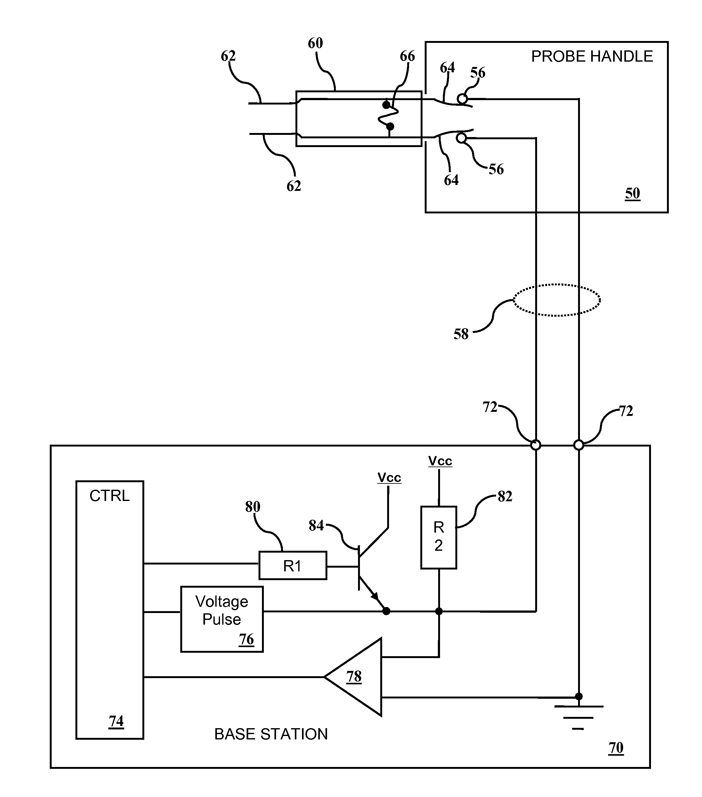
[0026]Referring to FIG. 1, a schematic view of a system of the present invention will be described. In this embodiment, a fuse 66 is embedded in the probe 60. In this embodiment, the fuse is shown bridging the two probe conductors 64, while in other embodiments having more than two conductors between the probe 60 and probe handle 50, other fuse arrangements are envisioned. The fuse 66 is an indicator that identifies whether the probe 60 has been previously used. If the fuse 66 is conductive, it is believed that the probe 60 has not been previously used. If the fuse 66 is blown (non-conductive), it is believed that the probe 60 has been previously used. In this embodiment, the probe 60 has two probe tip conductors 62 that are electrically coupled to connector pins 64 in the base of the probe 60. The connector pins 64 mate with connector pins 56 within the probe handle 50, which are in electrical communication with a base station 70 through a cable 58 or other means. In some embodimen...

second embodiment

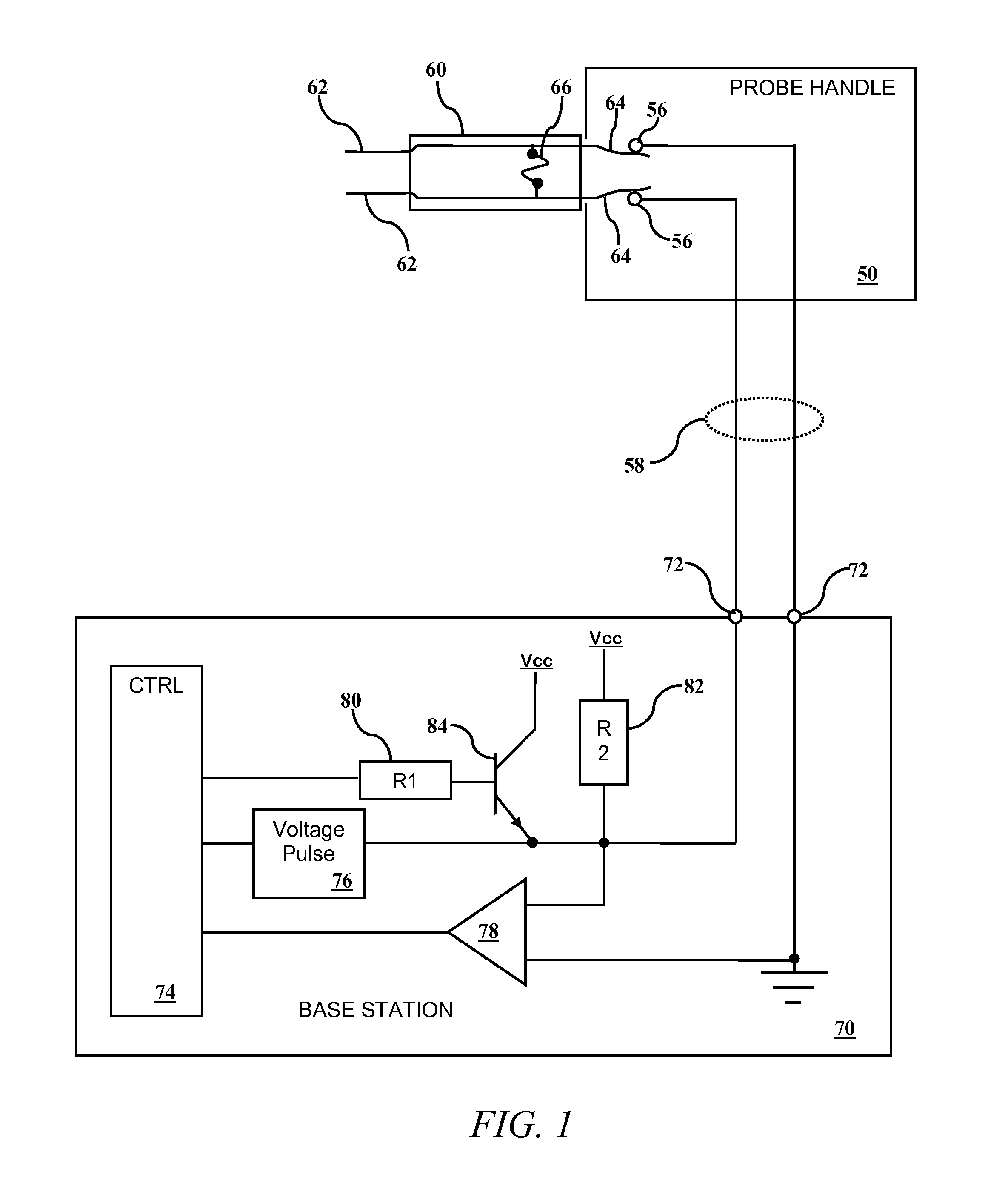
[0028]Referring to FIG. 2 along with FIG. 2A, FIG. 2B and FIG. 2C, a system of the present invention will be described. In this embodiment, an ID device 67 is embedded in the probe 60. In this embodiment, the ID device 67 is shown bridging the two probe conductors 64, while in other embodiments having more than two conductors between the probe 60 and probe handle 50, other ID device 67 arrangements are envisioned. The ID device 67 is an indicator of whether the probe 60 has been previously used. The ID device 67 has a unique or statistically unique characteristic that is detectable by the base station 70 through the probe handle 50. Many ID devices 67 are envisioned including tuned circuits such as capacitors, inductors and parallel or serial capacitors and inductors. In some embodiments, the ID device 67 is a ROM / EPROM / EEPROM / FLASH, preferably a serial version to reduce pin / conductor requirements. In all examples of ID devices 67, each device has a statistically unique characterist...

third embodiment

[0032]Referring to FIG. 3, a schematic view of a system of the present invention will be described. RFIDs 68 are known in the industry as are RFID readers. RFIDs (radio frequency identification devices) 68 contain a data stream that is usually unique, providing a serial number. The serial number is read by radio frequency (RF) radiation from the RFID reader 52 through a wireless connection. The RFID 68 uses parasitic RF energy to power itself and transmit its identification code or serial number. In some embodiments, the RFID reader 52 is integrated into the probe handle 50 (as shown in FIG. 3) while in other embodiments, it is integrated into the base station 70 or external to the base station 70. It is preferred that the RFID reader 52 be located in the probe handle 50 for several reasons. First, its close proximity to the probe 60 allows more accurate readings of the RFID 68 within the probe utilizing less transmission power. Second, because lower transmission power is used, the ...


PUM


Abstract

An application for preventing the reuse of a medical device includes a disposable medical device and a handle for accepting the disposable medical device. The handle physically supports the disposable medical device. A circuit for identifying the disposable medical device is imbedded within the disposable medical device and a circuit for reading a status of the identification is located in the handle. Whether the disposable medical device has been used is determined based upon the status.

Description

FIELD OF THE INVENTION[0001]This invention relates to the field of medical devices and more particularly to a system for preventing the reuse of sterile medical instruments.BACKGROUND OF THE INVENTION[0002]Many surgical procedures require the use of sterile probes or other devices that, once contacting a patient, are no longer sterile and should not be used with another patient. In some instances, because of the cost of such probes or devices, medical facilities attempt to clean or sterilize such probes or devices with heat, alcohol or other known procedures. Due to the nature of such probes and medical devices, it is not always possible to completely sterilize them because of their construction and / or their material composition. In such devices, the patient will not know that the device was previously used until a disease or infection occurs; when it is too late.[0003]Prior to the present invention, other methods of preventing reuse were employed. One method includes packaging the ...

Claims


Application Information

Patent Timeline
Patent Type & Authority Applications(United States)
IPC IPC(8): G06F17/00H01H85/00
CPCA61B18/1206A61B18/1402A61B2019/4873A61B2018/00875A61B2019/448A61B19/44A61B90/90A61B90/98A61B2090/0814
Inventor CAO, MICHAEL
Owner VASCULAR TECH
Why Eureka
Try Eureka