Universal ultraviolet/ IR/ visible light emitting module

a technology of light emitting modules and ultraviolet light, applied in the field of led light emitting devices for ultraviolet light, ir, and visible light, can solve the problems of inefficient methods of lighting up safety clothing, ineffective use, and high cost, and achieve the effect of saving power in the modul

Inactive Publication Date: 2009-03-12
WAINRIGHT LEE
View PDF9 Cites 31 Cited by
  • Summary
  • Abstract
  • Description
  • Claims
  • Application Information

AI Technical Summary

Benefits of technology

[0019]The first push button is depressed for a first time to blink the UV LEDs on and off along with the IR LED. The first push button is depressed for a second time to shut off the IR LED and UV LEDs and to turn on the white LED to act as a flashlight. The first push button is depressed for a third time to shut the power off to all LEDs. The second push button is depressed for the power output through a jack to power external items. The module has at least two sensors that are installed to provide valuable information and save power in the module.

Problems solved by technology

These methods of lighting up safety apparel are inefficient, costly, and add considerable weight and bulk using several “AA” batteries to keep them lit over a few hours time.
The LEDs and other light sources are exposed beyond the surface of the actual apparel leaving them in “harm's way” when actively participating in construction or emergency work conditions.
In the prior art, in order to light up surface areas of items such as clothing or backpacks, suitcases, exterior portions of transport vehicles, and the like, lights of some nature whether they be incandescent, LED, or EL require extensive wiring and have high current draws which result in shortened battery life.
Such devices do not have a way of shutting them off so their lifespan is quite short and they require a substantial amount of current compared to LEDs to operate.
Another problem that has not been adequately solved is having a device that transmits light energy for extended periods of time beyond days into weeks without need of battery replacement to assist rescuers in locating people who are stranded, hurt without mobility, lost, and are being sought after.
In addition, prior art methods contain physical switches mounted on exterior battery cases that are a big concern with electronic failure, are not waterproof, and can be damaged easily.

Method used


Image

  • Universal ultraviolet/ IR/ visible light emitting module
  • Universal ultraviolet/ IR/ visible light emitting module
  • Universal ultraviolet/ IR/ visible light emitting module

Examples


Embodiment Construction

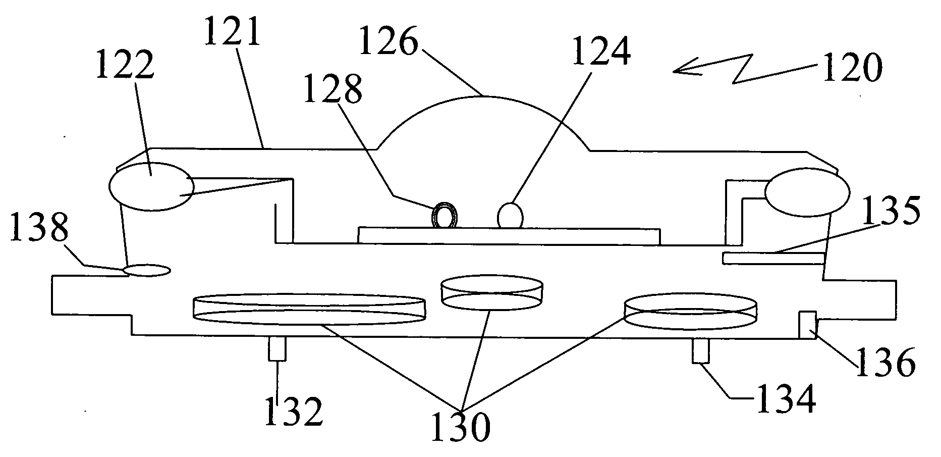
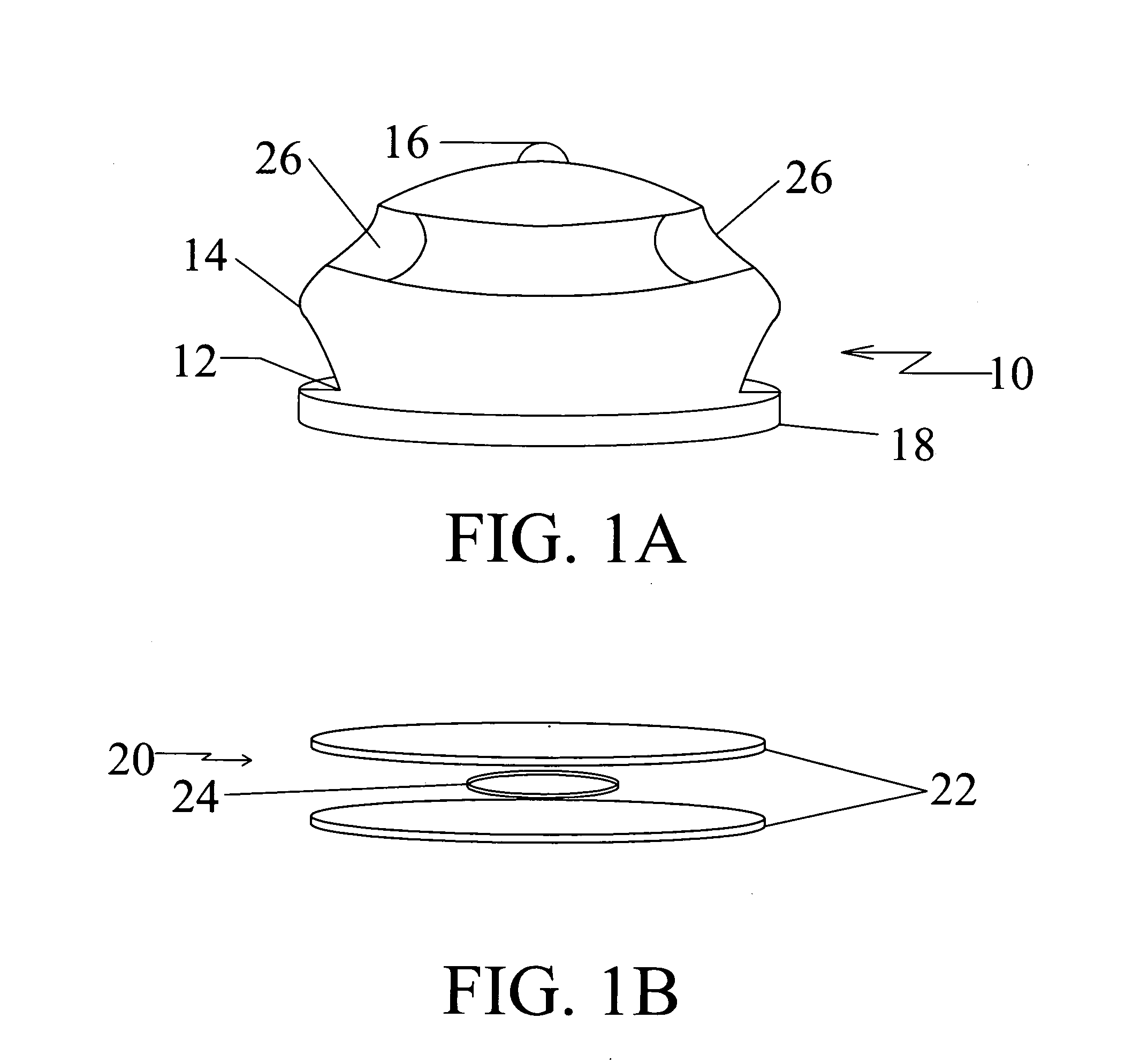
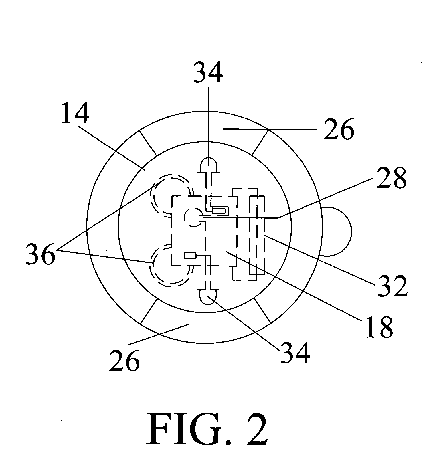
[0030]Referring to FIGS. 1A and 1B, a light emitting module 10 in accordance with a preferred embodiment of the present invention is shown. The module 10 includes a cylindrical base unit 12 and a body shell 14. The body shell 14 is securely coupled with the base unit 12. A loop 16 is securely coupled with the body shell 14 at a predefined position. The cylindrical base 12 defines a space for positioning a plurality of components of the module 10 at predefined positions. An outer surface of the base unit 12 is advantageously coated with a ferromagnetic material.

[0031]A rubber gasket is preferably positioned between the base unit 12 and the body shell 14. A bottom portion of the cylindrical base 12 protrudes outwards to define a circular flange 18. The module also includes a rounded base plate 20 that is defined by a pair of rounded rubber sheets 22 that encapsulate a rounded flat magnet 24. The thin rubber sheets 22 are coupled with each other with known sticking materials in the art...


PUM

PropertyMeasurementUnit
ultraviolet wavelengthaaaaaaaaaa
phosphorescenceaaaaaaaaaa
light energyaaaaaaaaaa

Abstract

A miniature, battery operated plastic module designed to project at least three different frequencies of energy from light emitting diodes is described. A first frequency is between 390 nm-420 nm just above harmful Ultraviolet Frequencies, a second frequency is between 850 nm-1200 nm in the infrared band and a third frequency is for a visible white light. The light emitting module has a base unit, the unit including a pulsed LED that emits an ultraviolet wavelength of light adapted to focus on a surface having phosphorescence means on the surface to activate the phosphorescence. The light emitting module may also have a base unit which includes a pulsed LED that emits an infrared wavelength of light adapted to penetrate a particular atmosphere. The module may also provide optional power for external items in addition to the three frequencies.

Description

RELATED APPLICATIONS[0001]This application claims the priority of U.S. Provisional Application No. U.S. Ser. No. 60 / 965,873, filed on Aug. 20, 2007.BACKGROUND OF THE INVENTION[0002]1. Field of the Invention[0003]The invention relates to light emitting devices, and more specifically, relates to LED light emitting devices for UV, IR, and visible light.[0004]2. Description of the Prior Art[0005]Light emitting devices implementing various techniques are known in the prior art. Ultraviolet lights have been used in a variety of light emitting devices in the prior art. The UV LEDs are generally applicable in smaller applications where only low voltage battery power is available. The prior art includes devices that use ultraviolet light generated by UV LEDs to excite phosphors in some portion of their structure.[0006]Many safety vests used on construction sites, DOT, and emergency personnel are primarily made of nylon or other fabrics containing UV reactive phosphor material and some in use...

Claims


Application Information

Patent Timeline
Patent Type & Authority Applications(United States)
IPC IPC(8): G01J3/10G01N21/64F21L4/00
CPCG01J1/08G01J1/32G01J3/10G01J3/108G01N21/8806
Inventor WAINRIGHT, LEE
Owner WAINRIGHT LEE
Why Eureka
Try Eureka