Molten metal reactor utilizing molten metal flow for feed material and reaction product entrapment

a technology of molten metal and reaction product, which is applied in the direction of liquid-gas reaction process, chemical/physical/physico-chemical process, chemical apparatus and processes, etc., can solve the problems of not being well suited to submerging other types of materials, and the plunger structure is not well suited for use in relatively high-volume waste treatment applications

Inactive Publication Date: 2009-03-12
WAGNER SHARON KAY
View PDF1 Cites 1 Cited by
  • Summary
  • Abstract
  • Description
  • Claims
  • Application Information

AI Technical Summary

Benefits of technology

[0006]According to the invention, the feed structure associated with the reactor introduces feed material into the molten reactant metal so that a flow of molten reactant metal immediately carries substantially all of the feed material and any initial reaction products into the treatment chamber. The feed material and reaction products are then trapped in the treatment chamber preferably by means of a suitable gravity trap structure. This combination of substantially immediate introduction into the treatment chamber and trapping in the treatment chamber helps ensure that the feed material and any intermediate reaction products have sufficient contact with the molten reactant metal to provide the desired chemical reactions, that is, the substantially complete chemical reduction of the feed material.
[0007]The desired contact with the reactant metal is enhanced according to the invention by inducing a swirling or vortex flow in the molten reactant metal in a feed chamber in which the feed material first makes contact with the molten reactant metal. This swirling flow may be produced in any suitable fashion, including by directing the molten metal into the feed chamber in an off center position, by driving the molten metal in the feed chamber with an impeller, or both. Also, a bowl-shaped feed chamber helps facilitate the desired swirling flow.

Problems solved by technology

A consistent issue with molten metal reactors is providing the necessary contact between the material to be treated or reacted, that is, the “feed material,” and the molten reactant metal.
Although the submerging structure works well with certain types of waste materials, such structures are not well suited for submerging other types of materials.
In particular, plunger structures are not well suited for use in relatively high-volume waste treatment applications in which relatively large quantities of loose or bulk feed materials, such as contaminated soils, for example, must be processed.

Method used


Image

  • Molten metal reactor utilizing molten metal flow for feed material and reaction product entrapment
  • Molten metal reactor utilizing molten metal flow for feed material and reaction product entrapment
  • Molten metal reactor utilizing molten metal flow for feed material and reaction product entrapment

Examples


Embodiment Construction

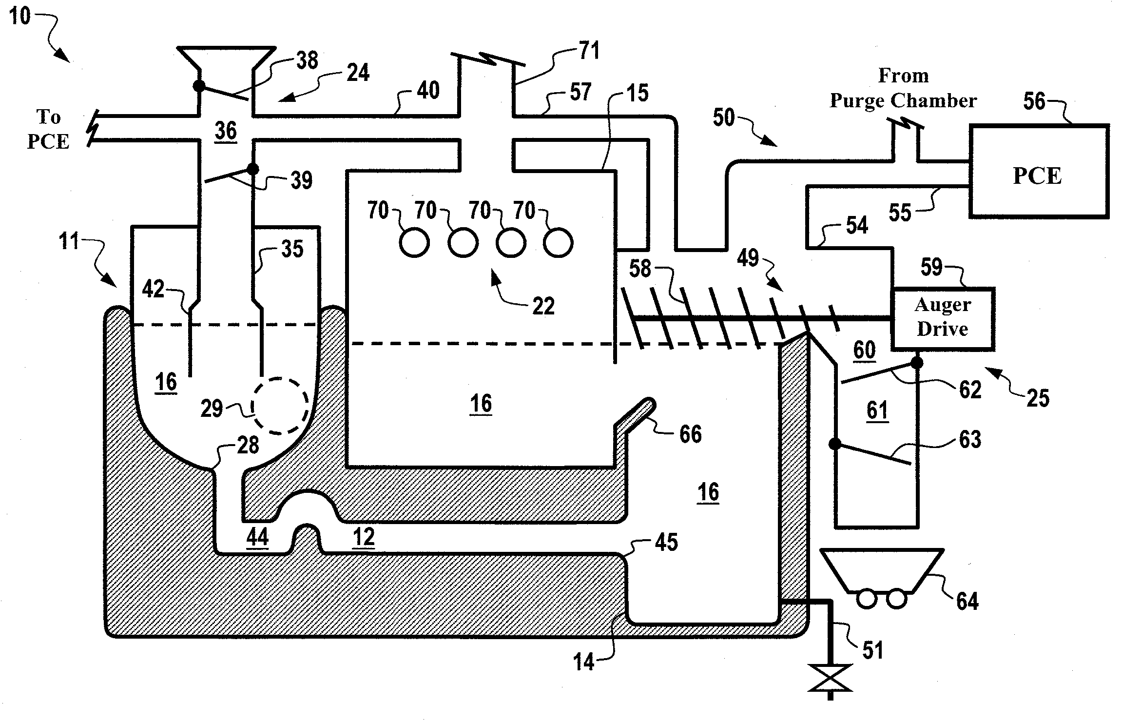
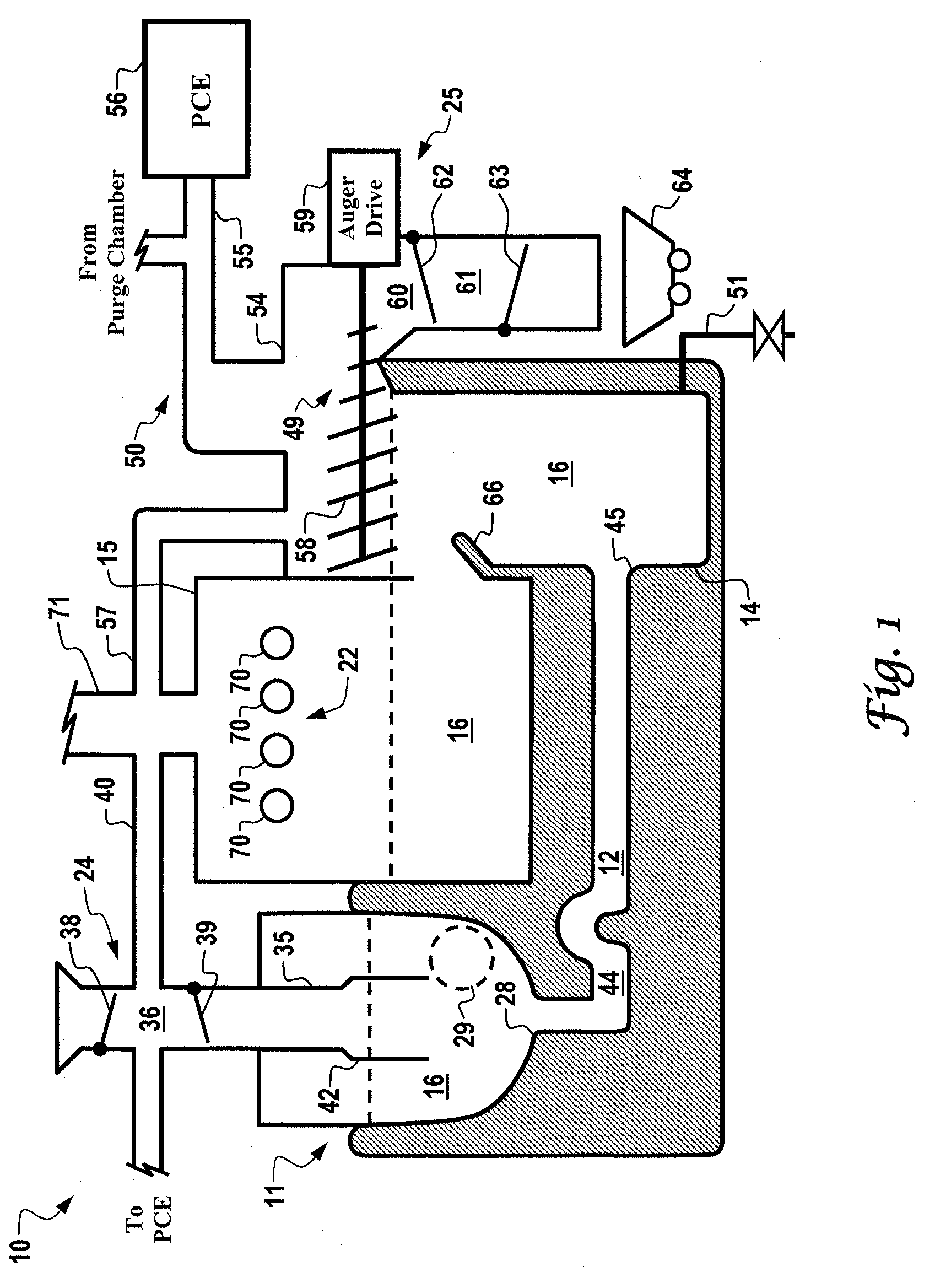
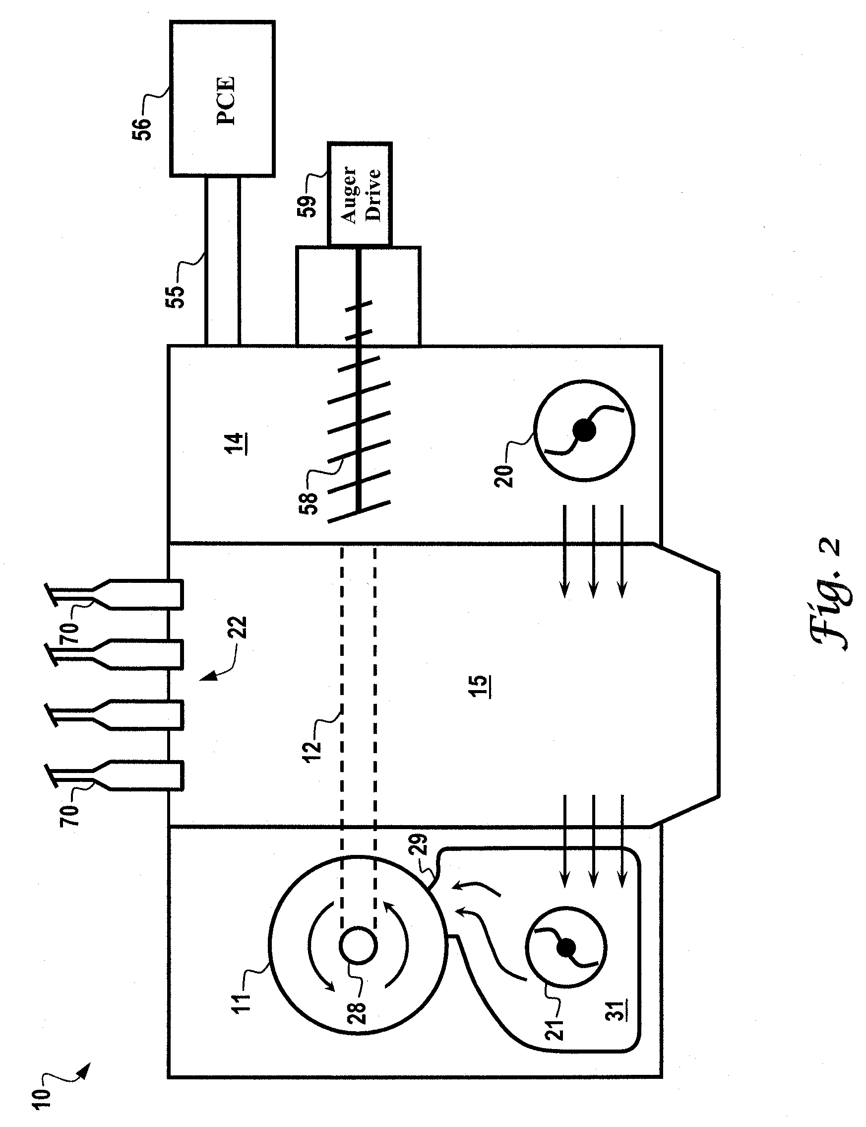
[0017]Referring particularly to FIGS. 1 and 2, a molten metal reactor 10 embodying the principles of the invention includes essentially four chambers including a bowl-shaped vortex or feed chamber 11, a treatment chamber 12, an output chamber 14, and a heating chamber 15. Each of these chambers is adapted to contain a molten reactant metal indicated by the reference numeral 16. The level of molten reactant metal 16 in feed chamber 11, output chamber 14 and heating chamber 15 is indicated by the dashed line in the respective chamber. Molten reactant metal 16 is heated to the desired temperature in heating chamber 15 and then transferred to feed chamber 11. From feed chamber 11, molten reactant metal 16 flows rapidly into treatment chamber 12 and then exits the treatment chamber into output chamber 14. From output chamber 14, molten reactant metal 16 returns to heating chamber 15 for reheating and recycling through the reactor 10. Reaction products are removed from reactor 10 through ...


PUM

PropertyMeasurementUnit
residence timeaaaaaaaaaa
chemical reductionaaaaaaaaaa
meltaaaaaaaaaa

Abstract

A molten metal reactor quickly entrains a feed material in the molten reactant metal and provides the necessary contact between the molten reactant metal and the feed material to effect the desired chemical reduction of the feed material. The reactor includes a unique feed structure adapted to quickly entrain the feed material into the molten reactant metal and then transfer the molten reactant metal, feed material, and initial reaction products into a treatment chamber. A majority of the desired reactions occur in the treatment chamber. Reaction products and unspent reactant metal are directed from the treatment chamber to an output chamber where reaction products are removed from the reactor. Unspent reactant metal is then transferred to a heating chamber where it is reheated for recycling through the system.

Description

CROSS-REFERENCE TO RELATED APPLICATIONS[0001]This application is a continuation of U.S. patent application Ser. No. 10 / 817,461 filed Apr. 2, 2004, entitled “Molten Metal Reactor Utilizing Molten Metal Flow for Feed Material and Reaction Product Entrapment,” which is a divisional of U.S. patent application Ser. No. 10 / 014,976 filed Dec. 11, 2001, entitled “Molten Metal Reactor Utilizing Molten Metal Flow for Feed Material and Reaction Product Entrapment,” now U.S. Pat. No. 6,717,026, which claimed priority from U.S. Provisional Patent Application Ser. No. 60 / 271,825 filed Feb. 27, 2001, entitled “Molten Metal Reactor Utilizing Molten Metal Flow for Feed Material and Reaction Product Entrapment.” The Applicant claims priority from U.S. patent application Ser. Nos. 10 / 817,461 and 10 / 014,976 under 35 U.S.C. §120, and claims priority from U.S. Provisional Patent Application Ser. No. 60 / 271,825 under 35 U.S.C. §119(e). The entire content of each of these applications is incorporated herei...

Claims


Application Information

Patent Timeline
Patent Type & Authority Applications(United States)
IPC IPC(8): C21C7/00B01J10/00B01J19/00B01J19/02C22B7/00C22B9/00
CPCA62D2203/10B01J10/005B01J19/0066Y10S423/12C22B7/001C22B9/00B01J19/02Y02P10/20
Inventor WAGNER, ANTHONY S.
Owner WAGNER SHARON KAY
Why Eureka
Try Eureka