Boundary acoustic wave device

Inactive Publication Date: 2009-03-12
MURATA MFG CO LTD
View PDF9 Cites 6 Cited by
  • Summary
  • Abstract
  • Description
  • Claims
  • Application Information

AI Technical Summary

Benefits of technology

[0010]To overcome the problems described above, preferred embodiments of the present invention provide a boundary acoustic wave device formed by laminating a plurality of media, wherein changes in characteristics due to temperature are significantly reduced.

Problems solved by technology

Therefore, it is difficult to obtain a boundary acoustic wave device having desired temperature characteristics.

Method used


Image

  • Boundary acoustic wave device
  • Boundary acoustic wave device
  • Boundary acoustic wave device

Examples


Embodiment Construction

[0034]Preferred embodiments of the present invention will be described below with reference to the drawings.

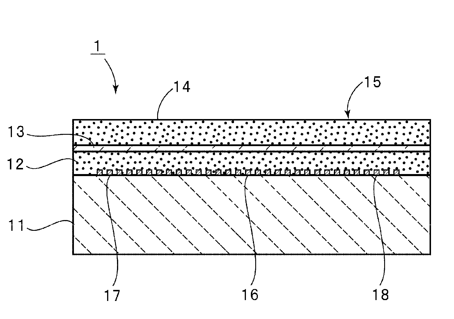
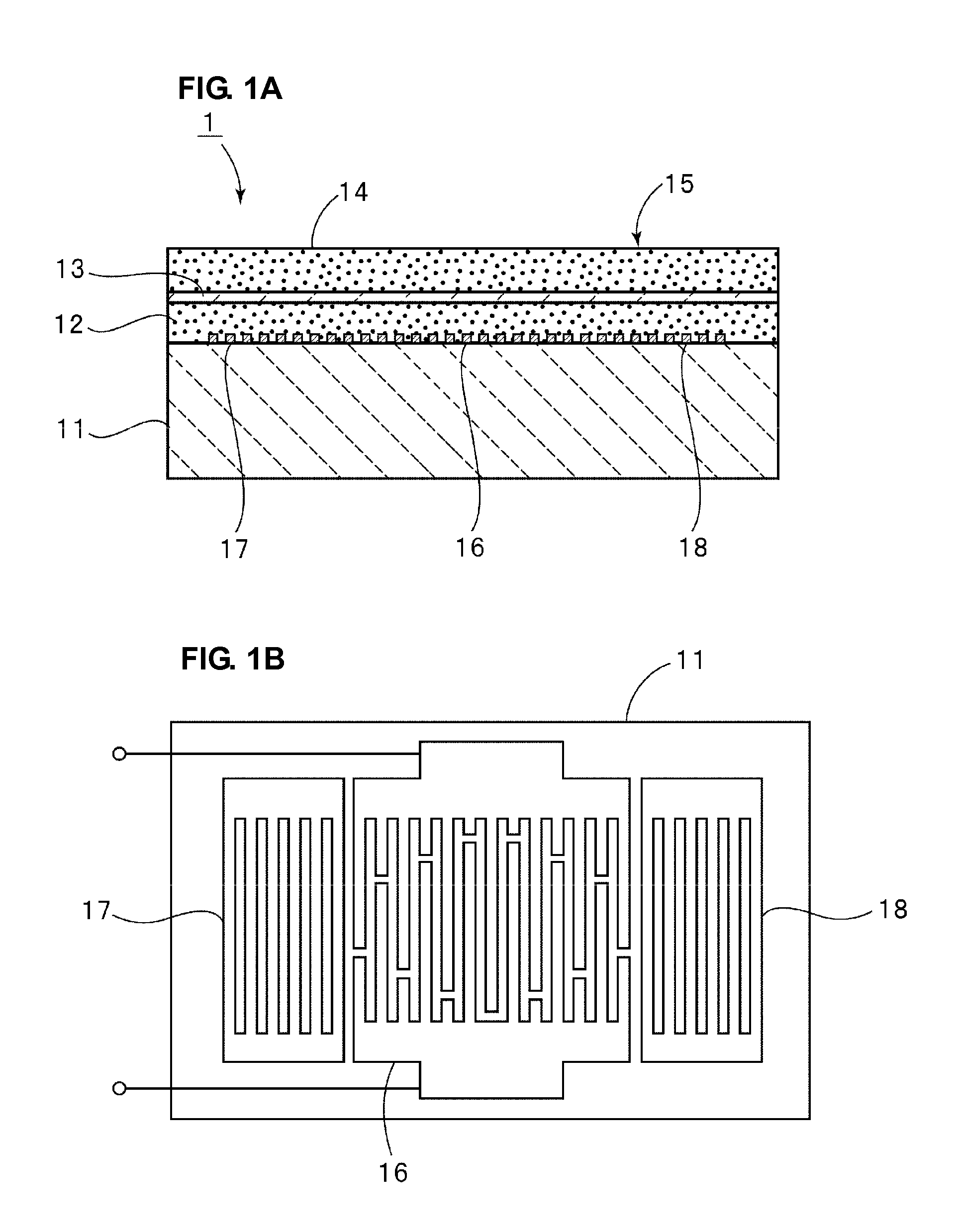
[0035]FIGS. 1A and 1B are a schematic sectional front view of a boundary acoustic wave device according to a preferred embodiment of the present invention and a schematic plan view showing an electrode structure.

[0036]A boundary acoustic wave device 1 includes a laminate 15 in which a first medium 11 to a fourth medium 14 are laminated in that order. Furthermore, an electrode structure shown in FIG. 1B is disposed at an interface between the first medium 11 and the second medium 12. That is, the above-described electrode structure includes an IDT electrode 16 and reflectors 17 and 18 disposed outside the IDT electrode 16 in a propagation direction of a boundary acoustic wave.

[0037]In the present preferred embodiment, the first medium 11 is preferably made of a 15°Y-cut X-propagation LiNbO3 substrate. The first medium 11 may be made by using LiNbO3 substrates having other cryst...


PUM


Abstract

A boundary acoustic wave device includes a first medium, a second medium, a third medium, and a fourth medium that are laminated in that order and, an electrode including an IDT electrode disposed at an interface between the first medium and the second medium, the temperature coefficient of delay time TCD of a boundary acoustic wave has a positive value, the fourth medium or the second medium has a positive temperature coefficient of sound velocity TCV, the first medium has a negative temperature coefficient of sound velocity TCV, and the sound velocity of transverse wave of the third medium is set to be less than the sound velocity of transverse wave of the fourth medium and / or the second medium.

Description

BACKGROUND OF THE INVENTION[0001]1. Field of the Invention[0002]The present invention relates to a boundary acoustic wave device used as, for example, resonators and filters. In particular, the present invention relates to a boundary acoustic wave device including an electrode which is disposed between a first medium and a second medium, and a third medium and a fourth medium are laminated on the second medium.[0003]2. Description of the Related Art[0004]In recent years, boundary acoustic wave devices have been used as resonators and band pass filters because the package structures thereof can be simplified.[0005]WO2004-070946 discloses a boundary acoustic wave device, wherein the electromechanical coefficient is relatively large, the propagation loss and the power flow angle are relatively small, and the temperature coefficient of resonant frequency TCF is within an appropriate range. Here, an IDT electrode is disposed at an interface between a first medium made of a piezoelectric ...

Claims


Application Information

Patent Timeline
IPC IPC(8): H01L41/04
CPCH03H9/02834H03H9/0222
Inventor KANDO, HAJIME
Owner MURATA MFG CO LTD
Why Eureka
Try Eureka