Antenna device and electronic appliance

Active Publication Date: 2018-12-06
MURATA MFG CO LTD
View PDF0 Cites 0 Cited by
  • Summary
  • Abstract
  • Description
  • Claims
  • Application Information

AI Technical Summary

Benefits of technology

This invention provides antenna devices that can maintain good quality even when a coil antenna is covered by a conductive material. These devices can be used in electronic appliances, improving communication with other electronic devices. The design includes a resonant circuit and a path for a resonant current to flow, which enhances the antenna's characteristics. The ground conductor pattern of the electronic appliance also acts as the first planar conductor of the antenna device, eliminating the need for a separate conductor. The electrically conductive portion of the casing or the shield layer of the display panel can also act as the second planar conductor, further reducing the size of the electronic appliance.

Problems solved by technology

In an antenna device in which a planar conductor, such as a ground conductor pattern, formed on a circuit board of an electronic appliance is used as a radiating body, when a coil antenna mounted on a circuit board is covered by a metal portion of the casing, magnetic flux that passes through the coil antenna does not flow in a large loop to outside the casing and the communication characteristics are severely degraded.

Method used


Image

  • Antenna device and electronic appliance
  • Antenna device and electronic appliance
  • Antenna device and electronic appliance

Examples


first preferred embodiment

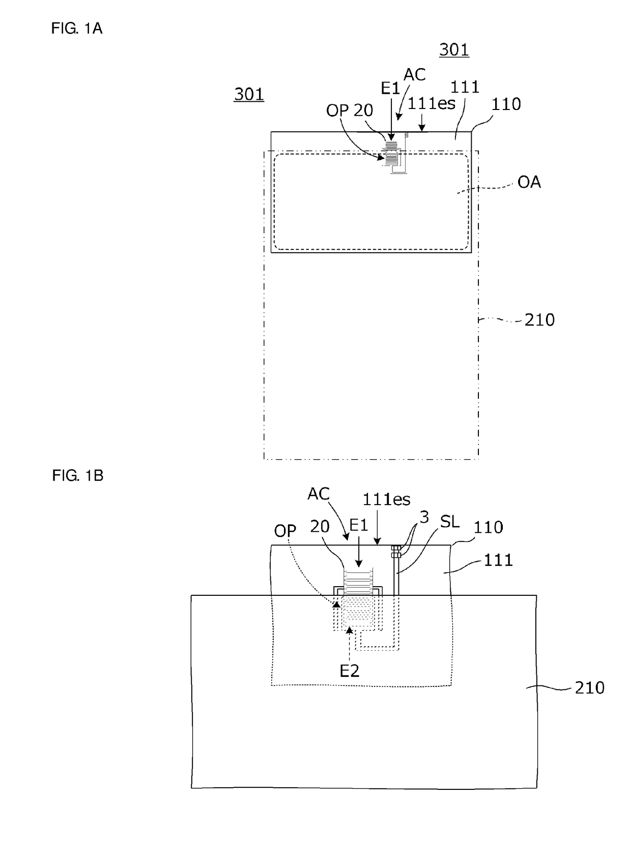
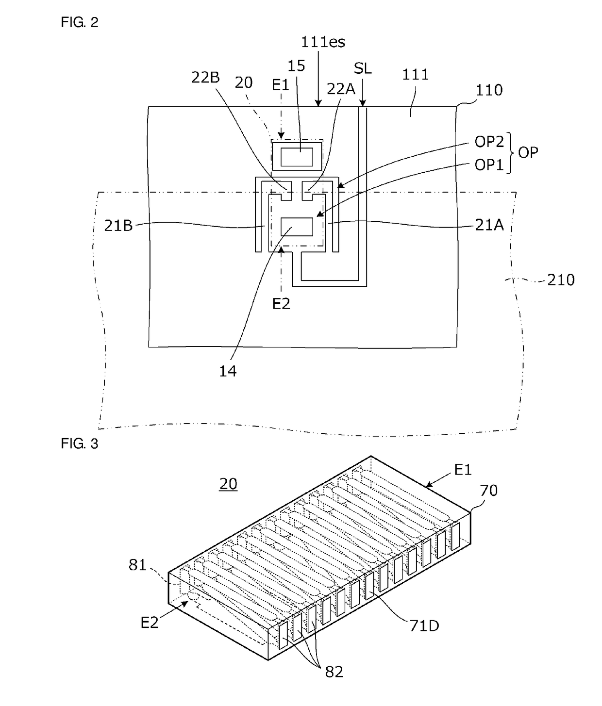
[0048]FIG. 1A is a plan view of an antenna device 301 according to a first preferred embodiment of the present invention, and FIG. 1B is a plan view of a coil element arrangement portion AC of the antenna device 301. FIG. 2 is a plan view of the coil element arrangement portion prior to mounting of a coil element 20 and capacitors 3.

[0049]The antenna device 301 includes a first planar conductor 111, a second planar conductor 210 that opposes the first planar conductor 111 in a parallel or substantially parallel arrangement, and the coil element 20.

[0050]As illustrated in FIG. 2, the first planar conductor 111 includes a first conductor opening OP1, a second conductor opening OP2, a conductor outer edge 111es, and a slit SL that connects the conductor opening OP and the conductor outer edge 111es to each other.

[0051]In the present preferred embodiment, the first planar conductor 111 is preferably a ground conductor pattern that is provided on a circuit board 110. The second planar co...

second preferred embodiment

[0123]In a second preferred embodiment of the present invention, an antenna device that includes a coil element not including an auxiliary conductor is described.

[0124]FIG. 16 is a plan view of a coil element mounting portion of the antenna device according to the second preferred embodiment. The coil element 20 is indicated by the two-dot chain line.

[0125]As illustrated in FIG. 16, the first planar conductor 111 includes a first conductor opening OP1, a second conductor opening OP2, a conductor outer edge 111es, and a slit SL that connects the conductor opening OP and the conductor outer edge 111es to each other.

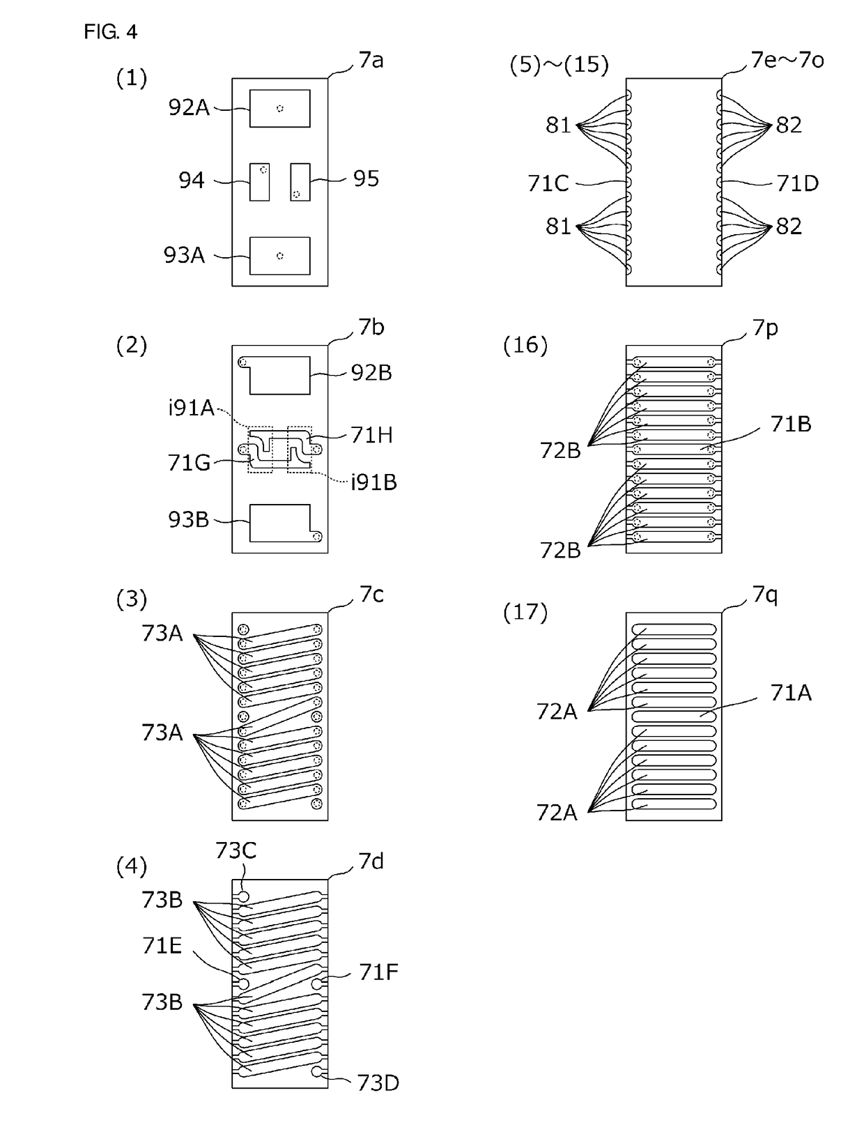
[0126]In the present preferred embodiment, inside the coil element 20, there is no auxiliary conductor having an approximately one turn rectangular or substantially rectangular loop shape defined by the line conductors 71A, 71B, 71E, 71F, 71G, and 71H and the end surface conductors 71C, 71D, and so on illustrated in FIG. 4. A line conductor portion 21 inside the conductor o...

third preferred embodiment

[0128]In a third preferred embodiment of the present invention, an antenna device in which there is no line conductor portion inside the conductor opening is described.

[0129]FIG. 17A is a plan view of an antenna device 303 of the third preferred embodiment, and FIG. 17B is a plan view of a coil element arrangement portion prior to mounting of a coil element. In the antenna device 303, the first planar conductor 111 includes the conductor opening OP, the conductor outer edge 111es, and the slit SL that connects the conductor opening OP and the conductor outer edge 111es to each other.

[0130]A portion of the conductor opening OP is positioned inside a conductor overlapping region in which the first planar conductor 111 and the second planar conductor 210 overlap in a plan view of the first planar conductor 111. In addition, the first coil opening end E1 of the coil element 20 is close to the conductor outer edge 111es in a region outside the conductor overlapping region. The second coi...


PUM


Abstract

An antenna device includes a first planar conductor, a second planar conductor that opposes the first planar conductor in a parallel or substantially parallel arrangement, and a coil element with a winding axis that extends in a direction parallel or substantially parallel to the first planar conductor and the second planar conductor, and includes a first coil opening end and a second coil opening end that opposes the first coil opening end. The first planar conductor includes a conductor outer edge, and a conductor opening including a portion that is continuous with the conductor outer edge. At least a portion of the conductor opening is positioned inside a conductor overlapping region. The first coil opening end of the coil element does not overlap the second planar conductor, and the second coil opening end of the coil element overlaps the conductor opening and the second planar conductor.

Description

CROSS REFERENCE TO RELATED APPLICATIONS[0001]This application claims the benefit of priority to Japanese Patent Application No. 2016-186559 filed on Sep. 26, 2016, Japanese Patent Application No. 2016-207267 filed on Oct. 21, 2016, and PCT Application No. PCT / JP2017 / 000961 filed on Jan. 13, 2017 and is a Continuation Application of PCT Application No. PCT / JP2017 / 034402 filed on Sep. 25, 2017. The entire contents of these applications are hereby incorporated herein by reference.BACKGROUND OF THE INVENTION1. Field of the Invention[0002]The present invention relates to an antenna device including a coil element, and to an electronic appliance including the antenna device.2. Description of the Related Art[0003]For example, Japanese Unexamined Patent Application Publication No. 2014-75775 discloses an antenna device in which a planar conductor of an electronic appliance is used as a portion of a radiating element. The antenna device is configured such that a coil antenna, which is connec...

Claims


Application Information

Patent Timeline
IPC IPC(8): H01Q7/00H01Q1/38H01Q1/42H01Q1/48H01Q1/44
CPCH01Q7/00H01Q1/38H01Q1/42H01Q1/48H01Q1/44H01Q1/243H01Q7/08H04B5/26H04B5/72H04B5/43H04B5/00
Inventor YAMAMOTO, MASAYOSHITENNO, NOBUYUKI
Owner MURATA MFG CO LTD
Why Eureka
Try Eureka