Switching regulator

Inactive Publication Date: 2009-03-12
RICOH ELECTRONIC DEVICES CO LTD
View PDF12 Cites 25 Cited by
  • Summary
  • Abstract
  • Description
  • Claims
  • Application Information

AI Technical Summary

Benefits of technology

[0008]This patent specification describes a novel switching regulator that includes a first switch, an inductor, a second switch, a controller to control a switching operation by switching the first switch and switching the second switch complementally to the first switch, and a reverse current detector to detect a reverse current that flows from an output terminal toward the second switch. The reverse curr

Problems solved by technology

As a result, performance efficiency of the switching regulator decreases.
When the supply current to the comparator 107 is increased, h

Method used


Image

  • Switching regulator
  • Switching regulator
  • Switching regulator

Examples


first embodiment

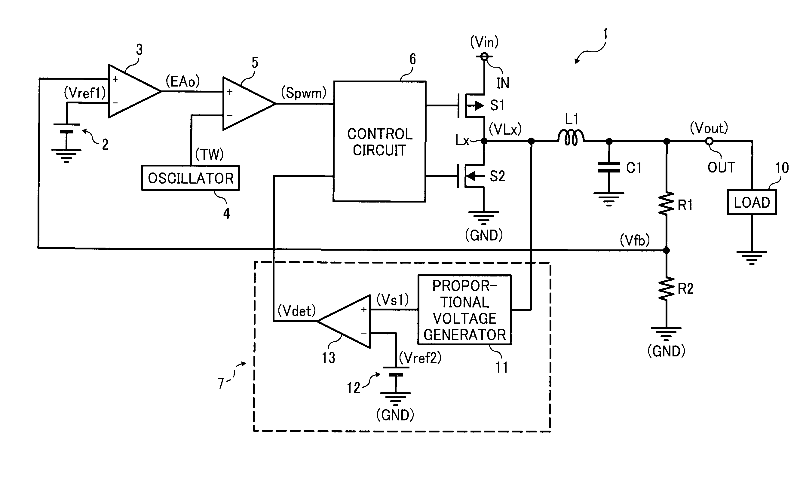
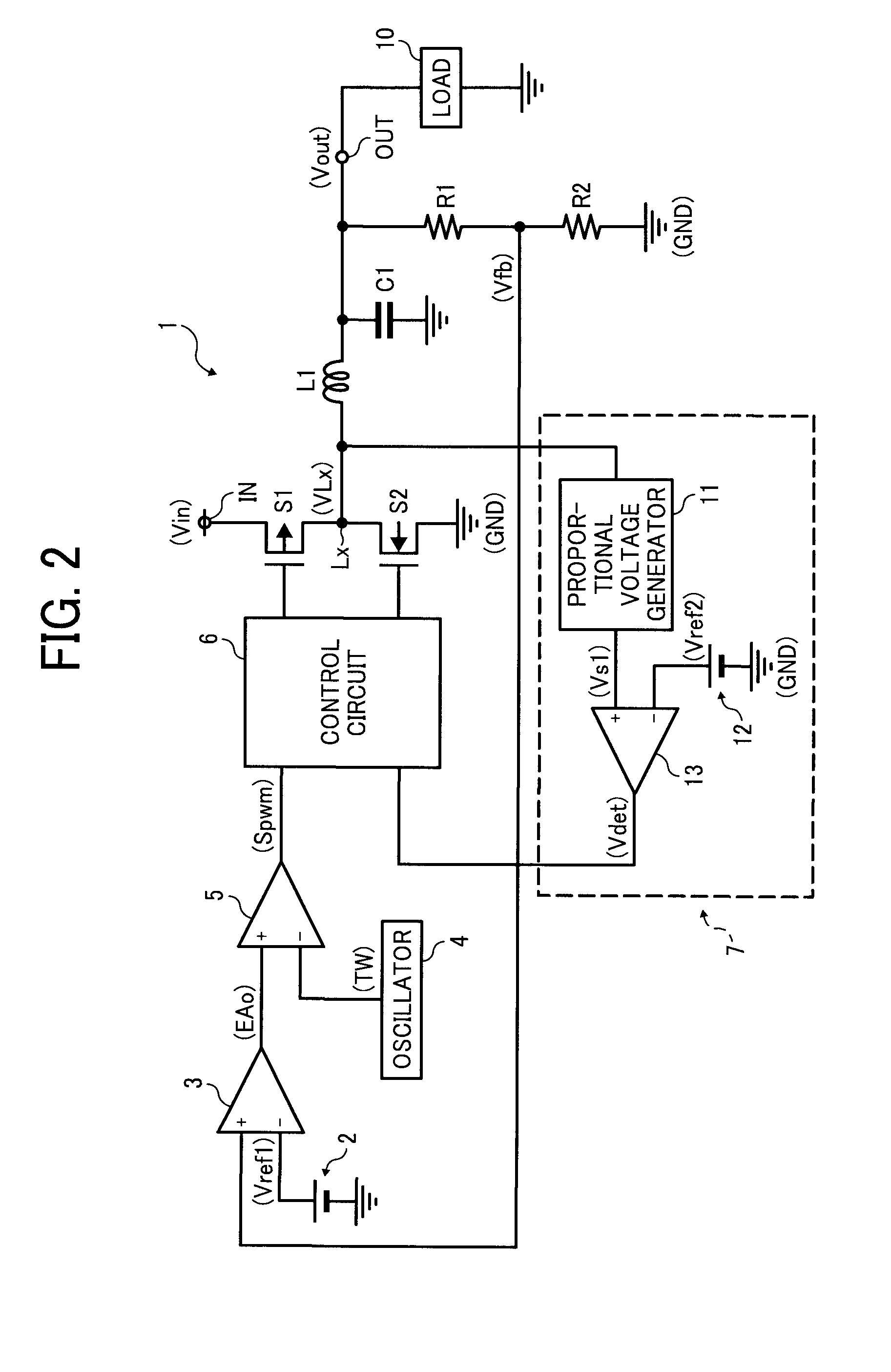
[0026]FIG. 2 is a circuit diagram of a switching regulator according to a first example embodiment. The switching regulator 1 is a step-down switching regulator that converts an input voltage Vin input at an input terminal IN to a predetermined voltage, and outputs the converted voltage as an output voltage Vout from an output terminal OUT to a load 10. The switching regulator 1 includes a switching transistor S1 and a synchronous rectification transistor S2. The switching transistor S1 is a PMOS transistor, and performs a switching operation to control output of the input voltage Vin. The synchronous rectification transistor S2 is an NMOS transistor.

[0027]Further, the switching regulator 1 includes a first reference voltage generator 2, resistors R1 and R2, an inductor L1, an error amplifier 3, an oscillator 4, a PWM comparator 5, a control circuit 6, and a reverse current detector 7. The resistors R1 and R2 detect the output voltage Vout, and the control circuit 6 controls the swi...

second embodiment

[0057]In the switching regulator according to the first example embodiment, the second reference voltage Vref2 is input to the inversion terminal of the comparator 13. However, in a switching regulator according to a second example embodiment, a reference voltage Vs2, which is obtained by adding a predetermined voltage V1 to the voltage VLx, is used for input to the inversion terminal of the comparator 13.

[0058]FIG. 6 is a circuit diagram of the switching regulator 1a according to the second example embodiment. In FIG. 6, identical reference characters are assigned to circuit members that are identical or similar to those shown in FIG. 2 and descriptions thereof are omitted.

[0059]The switching regulator 1a shown in FIG. 6 differs from the switching regulator 1 shown in FIG. 2 in that the second reference voltage generator 12 is removed and a reference voltage generator 21 is provided between the inversion terminal of the comparator 13 and the junction node Lx. Accordingly, the rever...

third embodiment

[0068]In the switching regulator according to the first example embodiment, the proportional voltage generator 11 generates and outputs a proportional voltage Vs1 proportional to the voltage VLx. In a switching regulator according to a third example embodiment, a proportional voltage Vs3 is created by multiplying the voltage VLx by a factor k, and a negative reference voltage −Vref3 is input to the inversion terminal of the comparator 13.

[0069]FIG. 9 is a circuit diagram of a switching regulator 1b according to the third example embodiment. In FIG. 9, identical reference characters are assigned to circuit members that are identical or similar to those shown in FIG. 2 and descriptions thereof are omitted.

[0070]The switching regulator 1b shown in FIG. 9 differs from the switching regulator 1 shown in FIG. 2 in that the proportional voltage generator 11 is replaced by a proportional voltage generator 31 which generates and outputs the proportional voltage Vs3 which is created by multip...


PUM


Abstract

A switching regulator includes a first switch, an inductor, a second switch, a controller to control a switching operation by switching the first switch and switching the second switch complementally to the first switch, and a reverse current detector to detect a reverse current that flows from an output terminal toward the second switch. The reverse current detector generates a proportional voltage that is proportional to a voltage at a junction node between the second switch and the inductor, and detects a generation or an indication of the reverse current based on the proportional voltage. The controller turns the second switch off to create a shutdown state when the reverse current detector detects the generation or the indication of the reverse current.

Description

TECHNICAL FIELD[0001]The present disclosure relates to a switching regulator, and more particularly, to a switching regulator capable of preventing reverse current.BACKGROUND ART[0002]Recently, energy saving has been actively promoted to protect the environment. For battery-powered portable equipment, such as mobile phones, digital cameras, and the like, energy efficiency is especially important to prolong battery life. Such portable equipment typically uses a switching regulator that includes an inductor because it is efficient and can be made compact.[0003]FIG. 1 is a circuit diagram of a known switching regulator. The switching regulator 100 is a step-down synchronous-rectification type switching regulator. In FIG. 1, the switching regulator 100 includes a switching transistor S101, a synchronous rectification transistor S102, an inductor L101, an output capacitor C101, comparators 103, 105, and 107, an oscillator 104, an output driver 106, and bleeder resistors R101 and R102. A ...

Claims


Application Information

Patent Timeline
IPC IPC(8): G05F1/00
CPCH02M3/1588Y02B70/1466H02M2001/0009Y10S323/908Y02B70/10H02M1/0009G05F1/70
Inventor NODA, IPPEI
Owner RICOH ELECTRONIC DEVICES CO LTD
Why Eureka
Try Eureka