
Image Forming Apparatus for Use in Backside Printing

Inactive Publication Date: 2009-03-12
RICOH KK
View PDF7 Cites 109 Cited by
  • Summary
  • Abstract
  • Description
  • Claims
  • Application Information

AI Technical Summary

Benefits of technology

[0011]It is a general object of at least one embodiment of the present invention to provide an image forming apparatus that substantially eliminates one or more problems caused by the limitations and disadvantages of the related art.
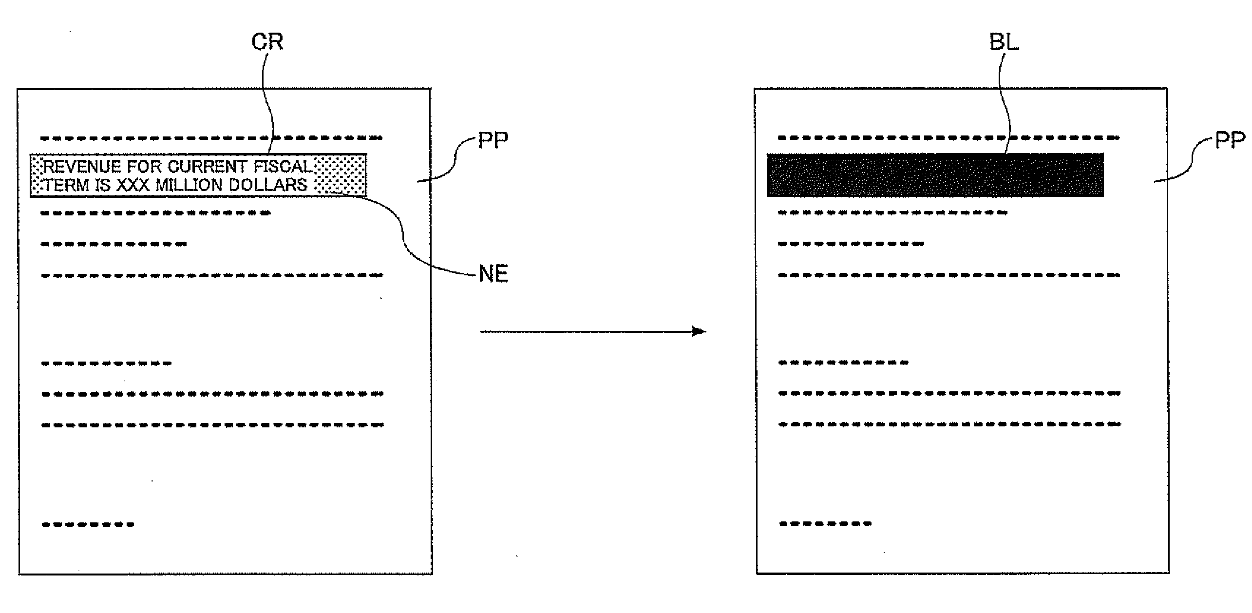
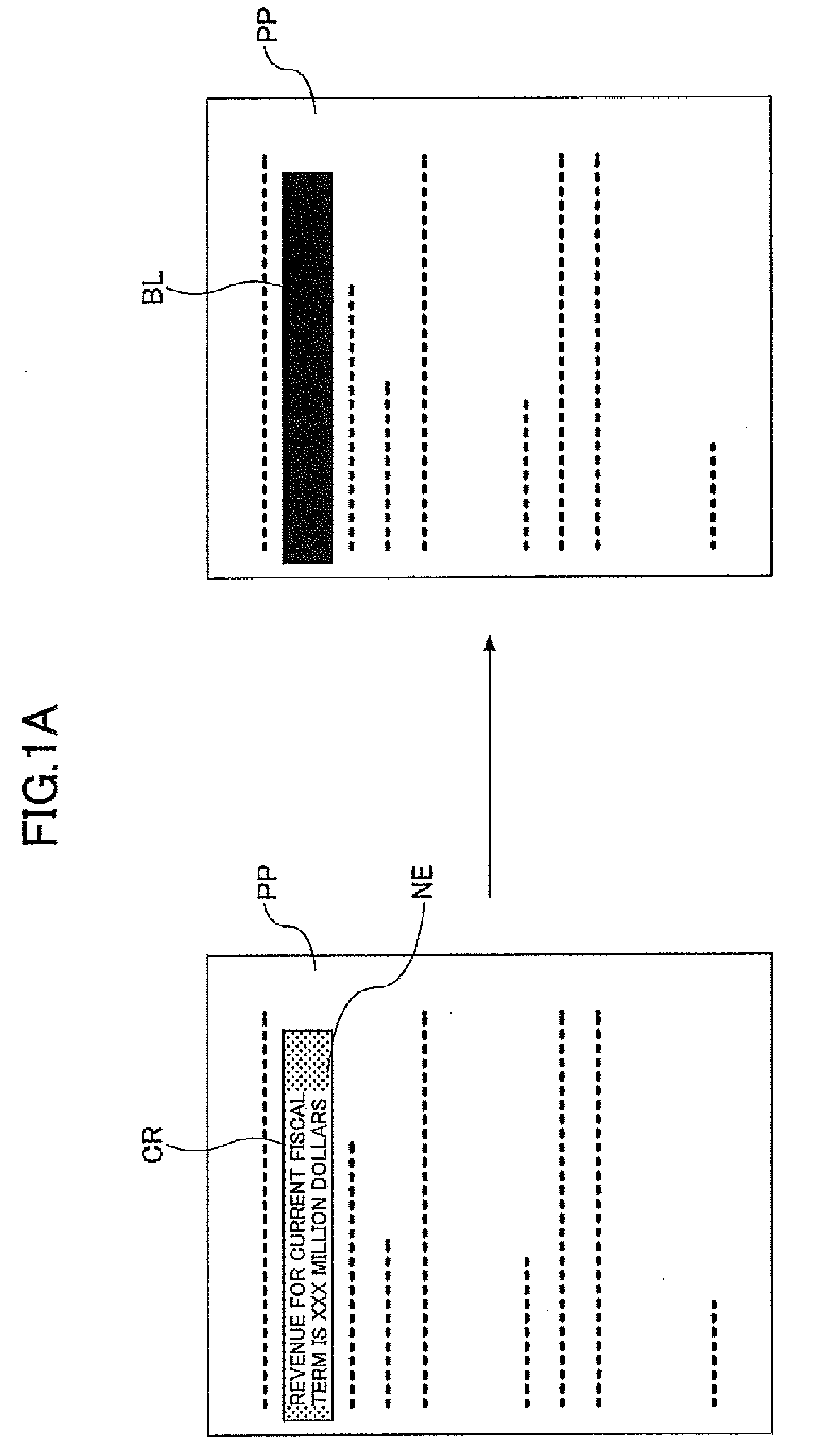
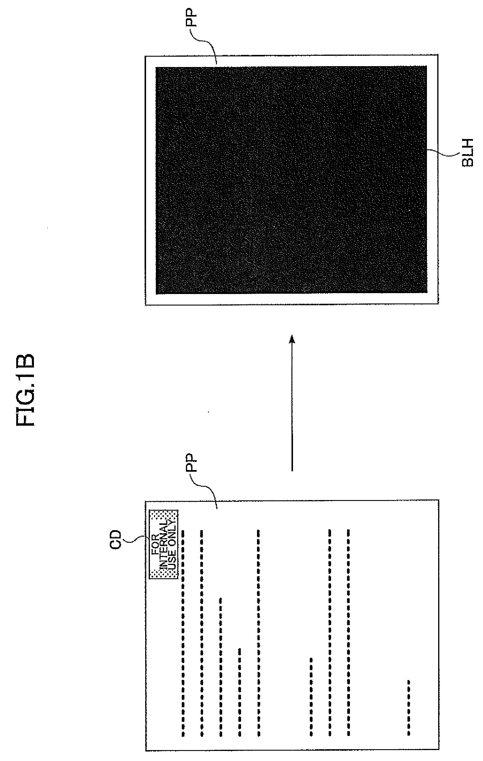
[0014]In an image forming apparatus according to at least one embodiment of the present invention, a document image for superimposition printing based on an image requested to be printed is generated or acquired from a source that requests printing, and is recorded as data associated with a paper sheet on which the requested image is printed. At the time of backside printing, the document image for superimposition printing associated with a paper sheet to be used for backside printing is obtained, and is printed on the pre-printed image printed on the paper sheet. With this arrangement, the document image for superimposition printing can make the pre-printed confidential information sufficiently illegible while containing blank areas unlike a solid pattern used in the conventional configuration. It is thus possible to reduce the amount of toner consumption while preventing the leakage of confidential information.

Problems solved by technology

In consideration of such usage, backside printing can save a significant amount of paper sheet consumption.
Also, there has been a number of cases in which paper sheets bearing confidential information thereon (i.e., confidential documents) are improperly distributed.
Against this background, the problems associated with the use of backside printing are not related to information newly printed on the backside, but are related to the leakage of confidential information that has already printed on the other side.
As a result, the leakage of confidential information may inadvertently occur.
However, this technology may also black out areas needing no blacking out for the purpose of protecting confidential information, thereby ending up consuming excessive amount of toner.
If all the spaces between characters or between character parts are to be blacked out, a large amount of toner will be consumed.

Method used


Image

  • Image Forming Apparatus for Use in Backside Printing
  • Image Forming Apparatus for Use in Backside Printing
  • Image Forming Apparatus for Use in Backside Printing

Examples


Embodiment Construction

[0029]In the following, embodiments of the present invention will be described with reference to the accompanying drawings.

[0030]

[0031]FIG. 2 is a drawing showing an example of blacking out on the side of a paper sheet that bears confidential information at the time of backside printing.

[0032]In this embodiment, QR codes 303 are printed separately from a confidential document at the centers of four margins at the top, bottom, left, and right of a paper sheet when the confidential document is printed. The QR codes 303 serve as code images inclusive of information regarding a document image for superimposition printing based on the confidential document image. The document image for superimposition printing included in the QR codes 303 may be a coarse image generated by reducing the image resolution of document contents printed on the paper sheet. Alternatively, such an image may be generated by performing an expansion process as many times as determined in advance with respect to the...


PUM


Abstract

An image forming apparatus includes an image obtaining unit configured to generate a document image for superimposition printing in response to an image requested to be printed or acquire the document image for superimposition printing from a source that requests printing, and an image recording unit configured to record the document image for superimposition printing as data associated with a paper sheet on which the requested image is printed.

Description

BACKGROUND OF THE INVENTION[0001]1. Field of the Invention[0002]The disclosures herein relate to an image forming apparatus such as an MFP (multifunction printer).[0003]2. Description of the Related Art[0004]For the purpose of resource saving and cost reduction, there has been an increasing number of users who use the blank side of print sheets to print images after the other side has already been used for printing. Such printing is sometimes referred to as “backside printing”. In most cases, print sheets are used for printing only on one side thereof, and will thereafter be discarded without being kept as a long lasting record. In consideration of such usage, backside printing can save a significant amount of paper sheet consumption.[0005]There has also been an increasing number of incidents in which confidential information such as personal information is leaked, which has resulted in an increase in awareness for security. Leakage of confidential information may occur in the form ...

Claims


Application Information

Patent Timeline
IPC IPC(8): G06F3/12
CPCG03G15/36G03G21/046G03G2215/049G03G2215/00586G03G2215/00919G03G2215/00299
Inventor INOKUCHI, SUMIHIRO
Owner RICOH KK
Learn More