Radiation scanning units including a movable platform

a scanning unit and moving platform technology, applied in the direction of material analysis using wave/particle radiation, instruments, applications, etc., can solve the problems of difficult to distinguish between, difficult to identify dangerous items, and difficulty in identifying thin sheets of explosive materials

Inactive Publication Date: 2009-03-12
VARIAN MEDICAL SYSTEMS
View PDF42 Cites 73 Cited by
  • Summary
  • Abstract
  • Description
  • Claims
  • Application Information

AI Technical Summary

Problems solved by technology

One disadvantage of radiographic imaging is that all items within the object in the path of the radiation beam are superimposed on the image.
If there are many items in the object, it may be difficult to distinguish among them.
The identification of dangerous items is thereby hampered.
Thin sheets of explosive materials may also be difficult to identify on a radiograph, particularly if they are oriented perpendicular to the scanning beam.
However, reconstruction of CT images of an object requires a large number of scans of the object at a plurality of angles.
Conducting a sufficient number of scans for CT reconstruction is time consuming.
Depending on the system used, CT imaging of an entire piece of luggage may be too slow for practical use in screening luggage in airports, for example.
While the smuggling of contraband, such as guns and explosives, onto planes in carry-on bags and in luggage has been a well known, ongoing concern, a less publicized but also serious threat is the smuggling of contraband across borders and by boat in large cargo containers.
Since only bags that fit through the tunnel may be inspected, such systems cannot be used to inspect cargo containers.
The low energies used in typical X-ray luggage and bag scanners, described above, are also too low to penetrate through the much larger cargo containers.
In addition, many such systems are too slow to economically inspect larger objects, such as cargo containers.
While having sufficient penetration, use of a pencil beam may be too slow to efficiently scan cargo containers.
While faster than a pencil beam, a fan beam may still be too slow to efficiently scan large objects at a reasonable rate.
Radiographic images of large objects such as cargo containers suffer from the same problems described above with respect to radiographic images of smaller objects such as luggage.
The CT scanning units used in airports for luggage and the like discussed above are not readily scaleable to the large sizes required to scan cargo containers.
Such large rotating units, carrying both the sources and the detectors, would be very expensive and would be difficult to operate and maintain.

Method used


Image

  • Radiation scanning units including a movable platform
  • Radiation scanning units including a movable platform
  • Radiation scanning units including a movable platform

Examples


Embodiment Construction

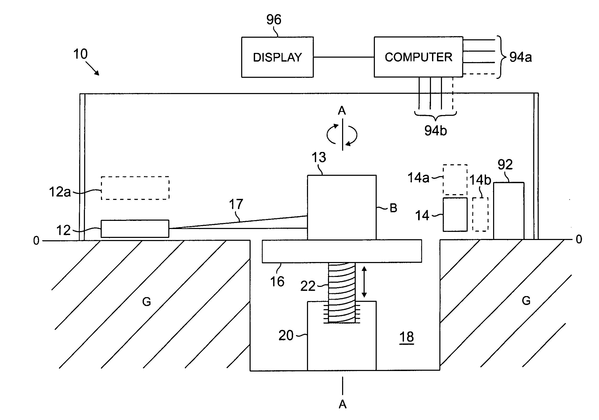
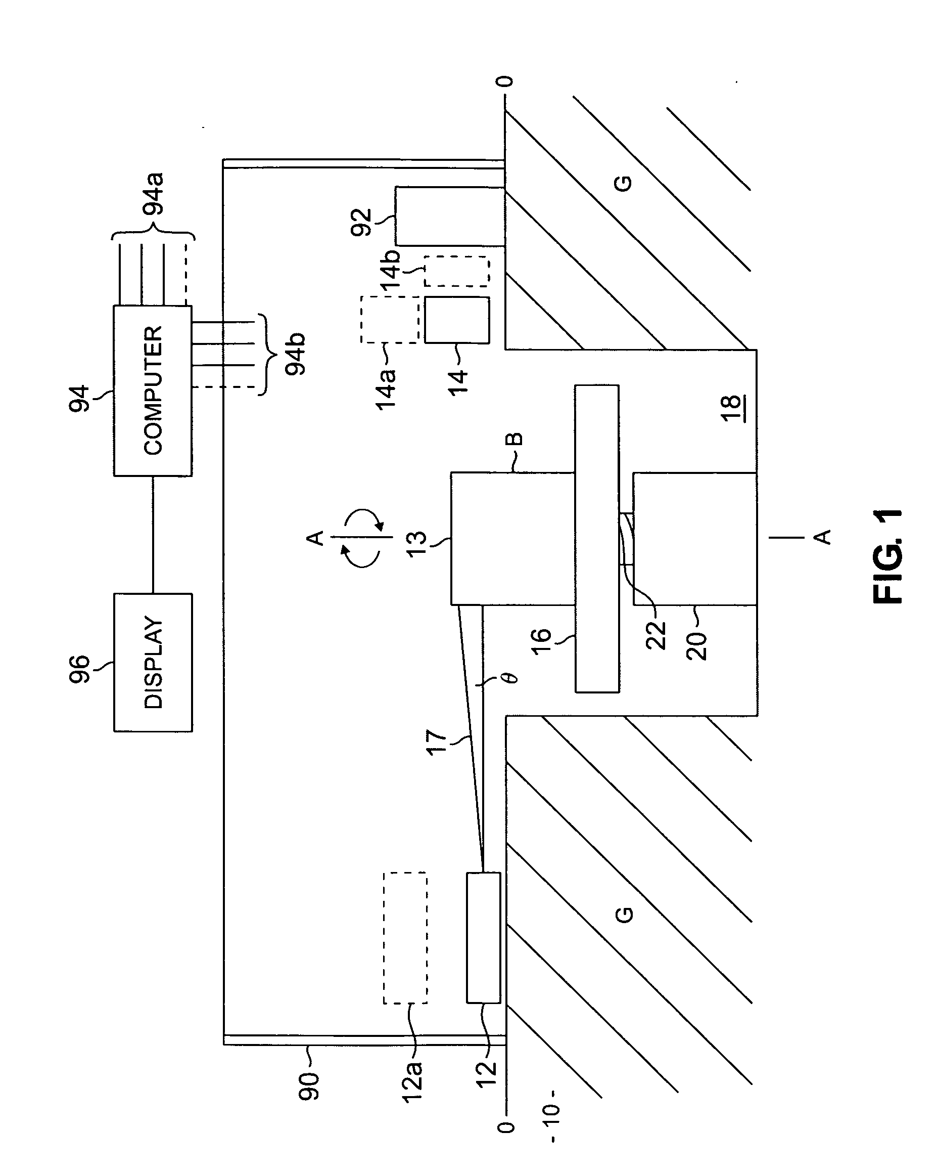
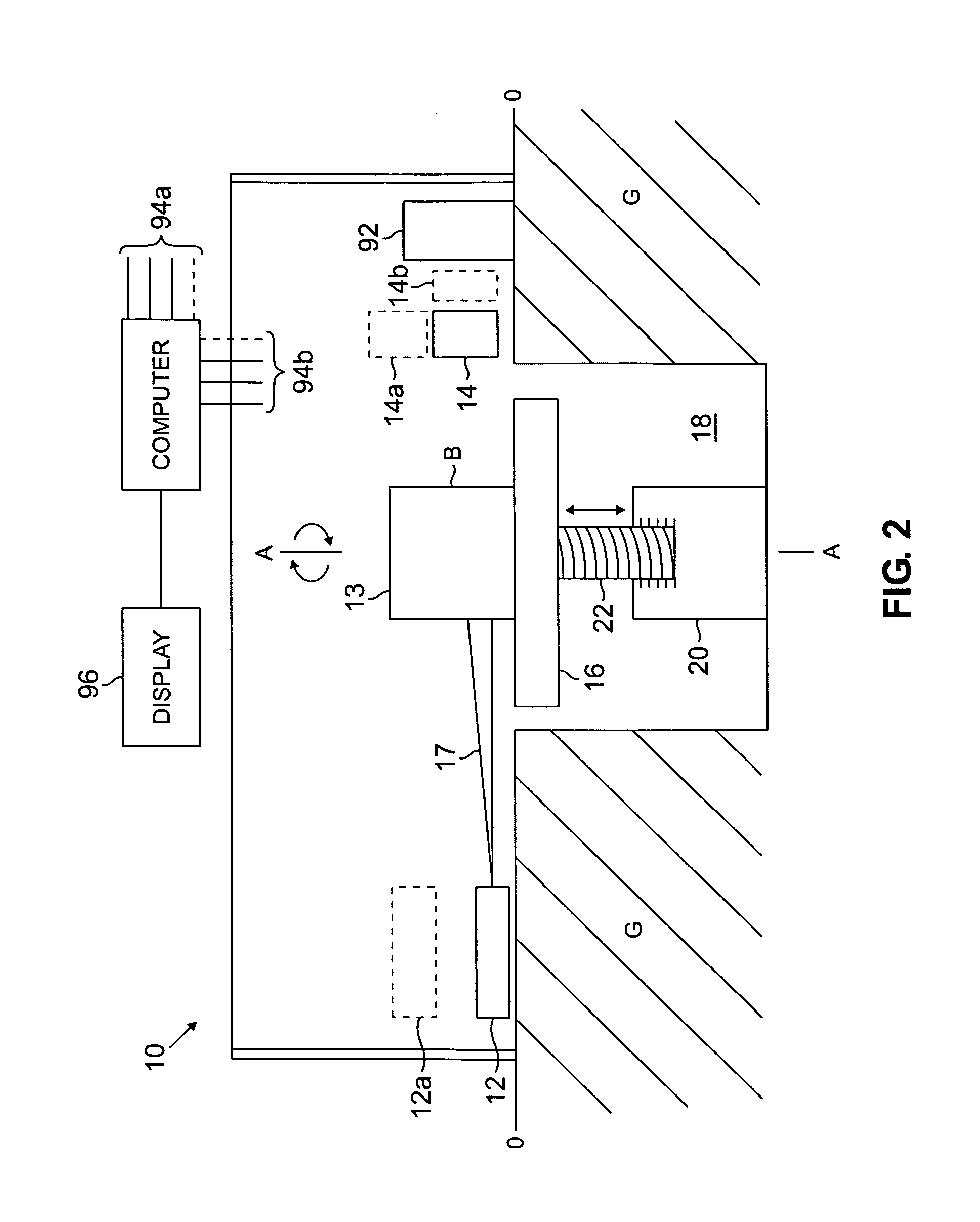
[0040]FIG. 1 is a side view of a scanning unit 10 according to one embodiment of the invention. In this embodiment, the scanning unit 10 comprises a source of radiation 12, such as X-ray radiation, to irradiate an object 13 being scanned, a detector 14 to detect radiation transmitted through the object 13 and a rotating / vertically displaceable platform 16 to support and position the object during scanning. The rotating / vertically displaceable platform 16 is between the source 12 and the detector 14. The source 12, along with suitable collimation, may emit a horizontal beam 17 of radiation and the detector 14 may extend horizontally. The horizontally extending beam may be a cone beam, as shown in FIG. 1, or a fan beam, for example. The object 13 may be a large object, such as a cargo conveyance (cargo container and pallets, for example). The object 13 may also be a smaller object, such as a piece of luggage or a carry-on bag, for example.

[0041]In this embodiment, the source 12 and th...


PUM

PropertyMeasurementUnit
widthaaaaaaaaaa
thicknessaaaaaaaaaa
average energyaaaaaaaaaa

Abstract

A scanning unit for inspecting objects comprises in one example a radiation source, a movable platform to support an object, and a detector positioned to receive radiation after interaction of radiation with the object. The platform is movable at least partially within a cavity defined, at least partially, below at least one of the source or the detector. In another scanning unit, a first conveyor conveys an object to a movable platform, and second and third conveyors convey the object from the platform. The second and third conveyors are at different vertical heights. In another scanning unit, images from an energy sensitive detector and a spatial detector are fused. In a method, scanning parameters during CT scanning are changed and images reconstructed before and after the change. In another method, an object is scanned with X-ray beams having first and second energy distributions, generated by the same X-ray source.

Description

[0001]The present application is a continuation of U.S. patent application Ser. No. 10 / 310,060, which was filed on Dec. 4, 2002 and will issue on Apr. 8, 2008 bearing U.S. Pat. No. 7,356,115. The present application is also a continuation-in-part of U.S. patent application Ser. No. 11 / 515,479, which was filed on Sep. 1, 2006, which is a continuation of U.S. patent application Ser. No. 10 / 202,273, which was filed on Jul. 24, 2002 and issued on Sep. 5, 2006 bearing U.S. Pat. No. 7,103,137.[0002]Radiation scanning of objects to identify contraband and, more particularly, radiation scanning of objects supported and moved by a platform.BACKGROUND OF THE INVENTION[0003]Radiation is commonly used in the non-invasive inspection of objects such as luggage, bags, briefcases and the like, to identify hidden contraband at airports and public buildings. The contraband may include hidden guns, knives, explosive devices and illegal drugs, for example. One common inspection system is a line scanner...

Claims


Application Information

Patent Timeline
Patent Type & Authority Applications(United States)
IPC IPC(8): G01N23/04
CPCG01N23/046G01N2223/419G01V5/005
Inventor SEPPI, EDWARD E.FORD, JOHNMARC, MARCEL
Owner VARIAN MEDICAL SYSTEMS
Why Eureka
Try Eureka