Fusing unit and image forming apparatus including the same

a technology of forming apparatus and fusing unit, which is applied in the direction of electrographic process apparatus, instruments, optics, etc., to achieve the effect of enhancing printing quality and minimizing thermal deformation

Inactive Publication Date: 2009-03-12
S PRINTING SOLUTION CO LTD
View PDF2 Cites 33 Cited by
  • Summary
  • Abstract
  • Description
  • Claims
  • Application Information

AI Technical Summary

Benefits of technology

[0012]Accordingly, an aspect of the present invention provides a fusing unit which can uniformly maintain an adhesive force between a heat radiating body and a nip plate, and an image forming apparatus including the same. Another aspect of the present invention provides a fusing unit which can minimize thermal deformation of a heat radiating body, and an image forming apparatus including the same. Still another aspect of the present invention provides a fusing unit which can uniformly maintain fusing temperature along a lengthwise direction thereof, and an image forming apparatus including the same. Yet another aspect of the present invention provides a fusing unit which can enhance the printing quality, and an image forming apparatus including the same.
[0014]Aspects of the present invention provide a fusing unit including: a driving roller; a belt which disposed to be driven by the driving roller; a nip plate disposed along a lengthwise direction of the driving roller with the belt disposed between the driving roller and the nip plate, the nip plate being pressed toward the driving roller to form a fusing nip; a heat radiating body disposed along the lengthwise direction to heat the nip plate by heat conduction; and a heat radiating body pressing member to press the heat radiating body toward the nip plate to prevent the heat radiating body from being spaced from the nip plate due to thermal deformation.
[0019]According to an aspect of the present invention, the fusing unit may further include a heat insulating member disposed between the supporting part and the heat radiating body to prevent heat from the heat radiating body from being transferred to the supporting part.

Problems solved by technology

Further, the non-uniform temperature along the lengthwise (X) direction causes a limit to an arrangement of a temperature sensor or requires multiple temperature sensors to prevent overheating of the fusing unit.

Method used


Image

  • Fusing unit and image forming apparatus including the same
  • Fusing unit and image forming apparatus including the same
  • Fusing unit and image forming apparatus including the same

Examples


Embodiment Construction

[0039]Reference will now be made in detail to the embodiments of the present invention, examples of which are illustrated in the accompanying drawings, wherein like reference numerals refer to like elements throughout. The exemplary embodiments are described below so as to explain the aspects of the present invention by referring to the figures.

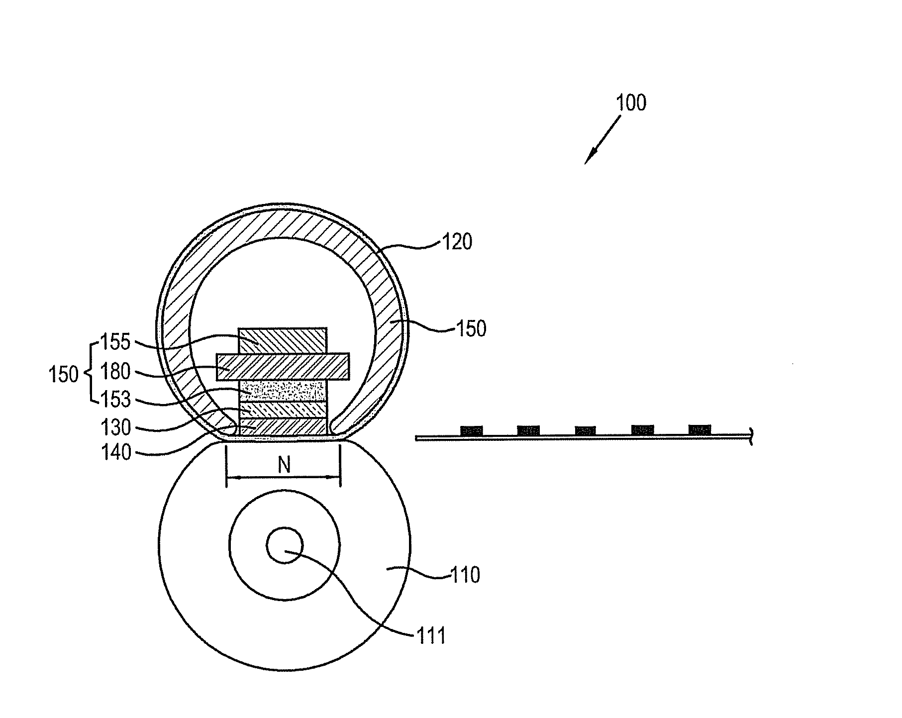
[0040]As shown in FIGS. 4 and 5, a fusing unit 100 according to an embodiment of the present invention includes a pressing roller 110; a belt 120, which is driven by the pressing roller 110, disposed about a belt guide 125; a nip plate 140, which is disposed along a lengthwise (X) direction of the pressing roller 110 with the belt 120 being disposed therebetween and forms a fusing nip (N); a heat radiating body 130, which is disposed along a lengthwise direction of the nip plate 140 and heats the nip plate 140; and a heat radiating body pressing member 150, which presses the heat radiating body 130 toward the nip plate 140.

[0041]The pressing ...


PUM


Abstract

A fusing unit, and an image forming apparatus including the same, includes: a driving roller; a belt disposed to be driven by the driving roller; a nip plate disposed along a lengthwise direction of the driving roller with the belt being disposed between the driving roller and the nip plate, the nip plate being pressed toward the driving roller to form a fusing nip; a heat radiating body disposed along the lengthwise direction to heat the nip plate by heat conduction; and a heat radiating body pressing member to press the heat radiating body toward the nip plate to prevent the heat radiating body from being spaced from the nip plate due to thermal deformation. The image forming apparatus includes: an image forming unit to form an image on a printing medium with a developer; and the fusing unit.

Description

CROSS-REFERENCE TO RELATED APPLICATIONS[0001]This application claims the benefit of Korean Patent Application No. 2007-92488, filed on Sep. 12, 2007, in the Korean Intellectual Property Office, the disclosure of which is incorporated herein by reference.BACKGROUND OF THE INVENTION[0002]1. Field of the Invention[0003]Aspects the present invention relate to a fusing unit and an image forming apparatus including the same, and more particularly, to a fusing unit that can minimize thermal deformation of a heat radiating body to enhance fusing efficiency, and an image forming apparatus including the same.[0004]2. Description of the Related Art[0005]In general, a fusing unit is employed in an image forming apparatus to form an image on a printing medium. The fusing unit applies heat and pressure to the printing medium to which a developer is applied to fuse the developer on the printing medium.[0006]The fusing unit may be classified as a roller type, which includes a heating roller and a p...

Claims


Application Information

Patent Timeline
Patent Type & Authority Applications(United States)
IPC IPC(8): G03G15/20
CPCG03G2215/2035G03G15/2053G03G15/2064
Inventor LEE, SEUNG-JUN
Owner S PRINTING SOLUTION CO LTD
Why Eureka
Try Eureka