Stage unit, drive table, and scanning exposure apparatus using same

a technology of scanning exposure and drive table, which is applied in the direction of instruments, printers, therapy, etc., can solve the problems of increasing the manufacturing cost of a projection optical system having high imaging performance, and achieve the effect of minimizing the total heat generation amount and high measurement accuracy

Inactive Publication Date: 2007-04-10
NIKON CORP
View PDF23 Cites 0 Cited by
  • Summary
  • Abstract
  • Description
  • Claims
  • Application Information

AI Technical Summary

Benefits of technology

[0012]In the scanning exposure apparatus, a large inertial force in the first direction as the scanning direction is applied to the fine adjustment stage particularly at the start and end of scanning. According to the stage unit of the present invention, however, an actuator having a small thrust is used as the electromagnetic actuator for driving the fine adjustment stage in the second direction (X direction or −X direction) because the inertial force applied to the fine adjustment stage in the second direction which is not the scanning direction can be almost neglected. With this arrangement, the shape and weight of the movable member of the electromagnetic actuator can be reduced. For this reason, the overall weight of the fine adjustment stage is reduced, thereby improving the control performance of the stage. In addition, the capacity of the coil of the electromagnetic actuator in the second direction can also be reduced. Since a heat generation amount from the coil is also decreased, heat deformation of each stage is minimized, thereby minimizing the adverse influence of heat to the measurement equipment for position measurement.
[0014]When the stationary member as a heat source is liquid-cooled, the total heat generation amount is minimized. It is mechanically easy to cool the stationary member in this manner.
[0015]The movable mirror fixed on the fine adjustment stage, and the interferometer for irradiating the measurement light beam on the movable mirror to detect the displacement of the fine adjustment stage with respect to the scanning stage are arranged, and the cooling fluid is circulated from the portion near the optical path of the light beam from the interferometer. In this case, when the cooling fluid has the largest cooling capability, the electromagnetic actuators are sequentially cooled from the portion near the optical path. For this reason, temperature adjustment of a gas on the optical path is stably performed, thereby maintaining a high measurement precision.
[0022]Even in this state, the push-back means is operating. Since the push-back means has a biasing force larger than the frictional force between the moving table and the base, the moving table is pushed back to the allowable movement range side. The switch means is set in an inoperative state, and driving of the moving table by the driving means is enabled. When, e.g., the control system of the driving means shifts to an error sequence upon operation of the switch means, and the driving means is driven upon completion of error processing, runaway of the moving table to the switch means side is prevented.
[0024]When the driving means is constituted by a linear motor, and the switch means operates to stop supplying the driving power to the linear motor, the linear motor has no driving force at all. Therefore, only the frictional force and the biasing force from the push-back means act on the moving table, thereby easily pushing back the moving table to the allowable movement range side.
[0029]The drive table of the present invention has the reference position detection means for detecting that the predetermined positions on the table reach the predetermined reference positions on the reference coordinate axes for the three displacements, displacements in the X and Y directions of the table, and the rotation amount θ about the θ axis perpendicular to the X and Y directions, and the calculation means for converting the detection values from the position detection means, which are obtained upon generation of the detection signals obtained from the reference position detection means into the coordinate values on the reference coordinates. For this reason, origin detection with respect to the reference coordinate axes of the drive table can be precisely performed.

Problems solved by technology

However, this results in an increase in manufacturing cost of a projection optical system having high imaging performance on the entire surface of the wide exposure field.

Method used


Image

  • Stage unit, drive table, and scanning exposure apparatus using same
  • Stage unit, drive table, and scanning exposure apparatus using same
  • Stage unit, drive table, and scanning exposure apparatus using same

Examples


first embodiment

[0065]The first embodiment associated with a stage unit according to the present invention will be described below with reference to FIGS. 5 to 7. In this embodiment, the present invention is applied to the reticle stage of a step and scan type projection exposure apparatus. The same reference numerals as in FIGS. 1 to 4 denote the same parts in FIGS. 5 to 7, and a detailed description thereof will be omitted.

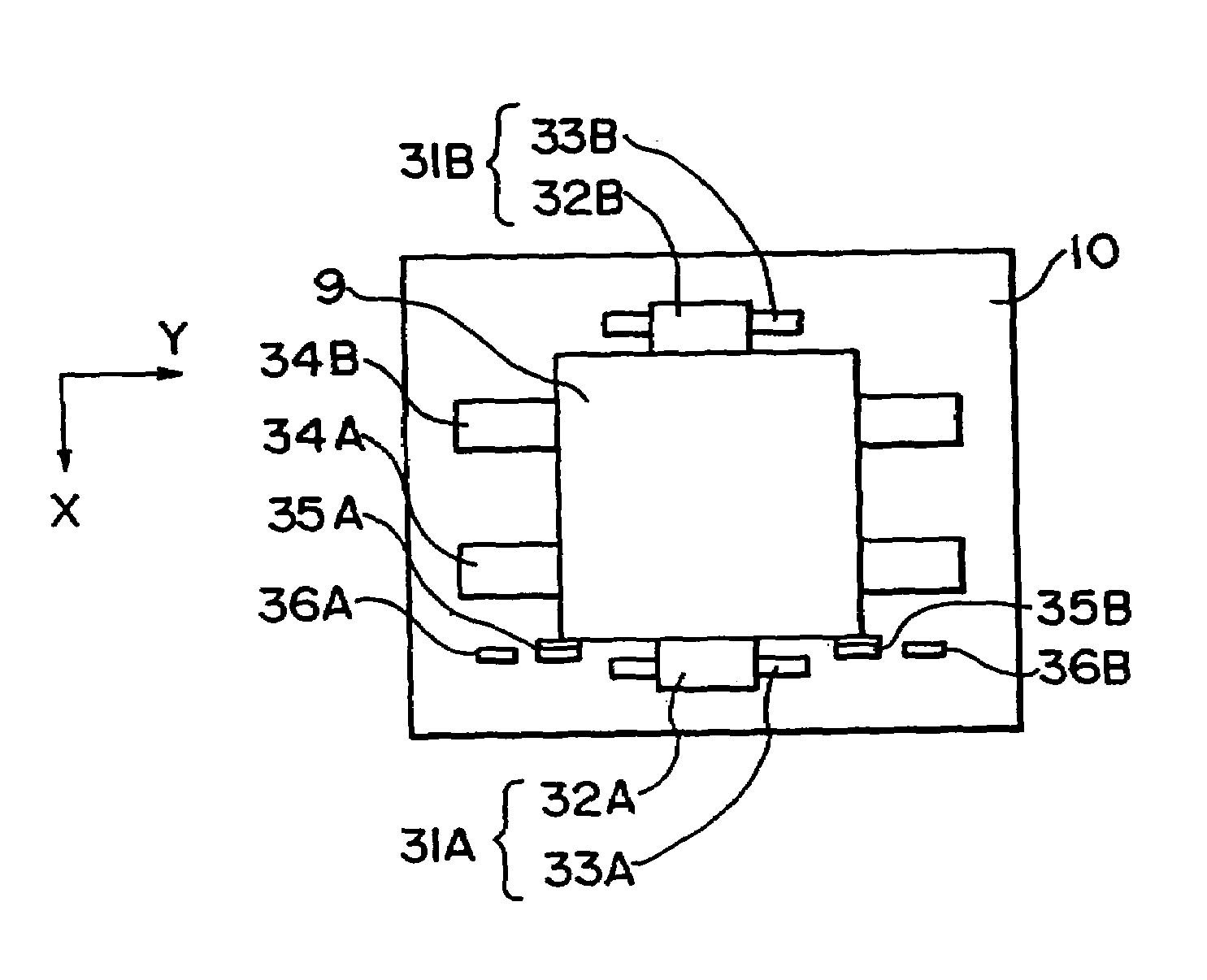
[0066]FIG. 5 is a plan view of the reticle stage of this embodiment. Referring to FIG. 5, a scanning stage 9 is mounted on a base 10 to be slidable in the Y direction along linear guides 34A and 34B. The scanning stage 9 is driven by linear motors 31A and 31B in the +Y or −Y direction with respect to the reticle base 10. A Y axis movable mirror 45 is fixed at the end portion of the scanning stage 9 in the Y direction. A laser beam from an external laser interferometer 44 is irradiated on the movable mirror 45 to be parallel to the Y axis, as indicated by an optical path 46. The...

second embodiment

[0090]The second embodiment associated with the stage unit according to the present invention will be described below with reference to FIGS. 8 to 13. In this embodiment, the present invention is applied to the reticle stage of a step and scan type projection exposure apparatus. The same reference numerals as in FIGS. 1 to 4 denote the same parts in FIGS. 8 and 9, and a detailed description thereof will be omitted.

[0091]FIG. 8 is a plan view of the reticle stage of this embodiment. Referring to FIG. 8, a scanning stage 9 is mounted on a base 10 to be slidable in the Y direction along linear guides 34A and 34B. The scanning stage 9 is driven by linear motors 31A and 31B in the +Y or −Y direction with respect to the base 10. A sliding portion 9a (FIG. 9) is formed on the lower surface of the scanning stage 9 so as to oppose one linear guide 34A while a sliding portion 9b (FIG. 13) is formed to oppose the other linear guide 34B. Bearings 90 are interposed between the linear guides 34A ...

third embodiment

[0123]FIG. 19 is a plan view for explaining the arrangement of the third embodiment associated with the drive table of the present invention. FIG. 20 is a plan view for explaining the arrangement of origin detection in FIG. 19. As shown in FIG. 19, the two-dimensional position (including the rotational direction) of a stage 110 of the drive table is always detected by an interferometer unit consisting of three interferometers at a resolving power of, e.g., 0.02 μm.

[0124]The interferometer unit is constituted by an X interferometer 101A, a Y interferometer 101B, and a θ interferometer 101C. A plane including the three measuring axes (e.g., the central lines of laser beams) is arranged to be parallel to the stage 110 of the drive table. The measuring axis of the X interferometer 101A and that of the Y interferometer 101B are arranged to be accurately perpendicular to each other. The θ interferometer 101C is arranged to be symmetrical with respect to the Y axis of an orthogonal coordin...


PUM

PropertyMeasurementUnit
driving currentaaaaaaaaaa
sizeaaaaaaaaaa
areaaaaaaaaaaa

Abstract

An exposure method for manufacturing a liquid crystal display utilizes a scanning exposure apparatus to expose a pattern of a mask onto a glass plate. The exposure method includes a step of moving a mask stage that holds the mask in a scanning direction by a first electromagnetic actuator. The first electromagnetic actuator moves the mask stage associating with a guide member that extends in the scanning direction. The method also includes the step of moving the mask stage in a non-scanning direction different from the scanning direction by a second electromagnetic actuator. The second electromagnetic actuator moves the mask stage associating with no guide member, and a moving distance in the non-scanning direction by the second electromagnetic actuator is shorter than a moving distance in the scanning direction by the first electromagnetic actuator.

Description

[0001]This is a Division of application Ser. No. 09 / 139,296 filed Aug. 25, 1998 now abandoned, which in turn is a Continuation of application Ser. No. 08 / 935,445 filed Sep. 23, 1997 (now U.S. Pat. No. 5,850,280), which in turn is a Continuation of application Ser. No. 08 / 490,497 filed Jun. 14, 1995 (now abandoned). The entire disclosure of the prior applications is hereby incorporated by reference herein in its entirety.BACKGROUND OF THE INVENTION[0002]1. Field of the Invention[0003]The present invention relates to a stage unit having a means for limiting the moving range of a moving table on which a target positioning object is mounted, a drive table driven by a linear motor and capable of easily performing origin detection, and a scanning exposure apparatus for manufacturing semiconductor elements or the like by using the same.[0004]2. Related Background Art[0005]To manufacture semiconductor elements, liquid crystal display elements, or the like by using the photolithography techn...

Claims


Application Information

Patent Timeline
Patent Type & Authority Patents(United States)
IPC IPC(8): G03B27/42G03B27/32G03B27/62G03F7/20
CPCG03F7/70358G03F7/70716G03F7/70725G03F7/70858G03F7/70875
Inventor HORIKAWA, HORITO
Owner NIKON CORP
Why Eureka
Try Eureka