
Fastening device

a technology of fastening device and female screw, which is applied in the direction of fastening means, sheet joining, couplings, etc., can solve the problems of increasing the kinds of bolts, affecting the tight affecting the smoothness of the female screw, so as to achieve the effect of reducing costs and easy imparting

Inactive Publication Date: 2009-03-12
AOYAMA SEISAKUSHO CO LTD
View PDF8 Cites 20 Cited by
  • Summary
  • Abstract
  • Description
  • Claims
  • Application Information

AI Technical Summary

Benefits of technology

[0008]An objective of the present invention is to solve the problems of the prior arts described above, and to provide a fastening device which includes a bolt having a male screw portion long in length but is free from any troubles caused by a pitch deviation, and is capable of securely tightening two members spaced from each other at various distances using such bolts having a unified below-neck length and a unified male screw portion length.
[0012]However, in the fastening device according to the present invention, an elastic body layer is formed on the inner peripheral surface of a movable spacer. The elastic body layer exhibits a torque transmitting function as well as a pitch deviation absorbing function simultaneously when the male screw portion of the bolt is screwed therein. Owing to this elastic body layer, no pitch deviation occurs even if the male screw portion of the bolt is screwed to the elastic body layer of the movable spacer and the first member simultaneously. For this reason, unlike the conventional cases, the male screw portion of the bolt is not required to be short in length. Thus, the male screw portion of the bolt can be formed to be long in length, and this bolt having the unified male screw portion length is applicable to tightening the first member and the second member to each other not only in the case where the distance between the first member and the second member is long as a matter of course, but also in the case where the distance is short. As a result, there is no need of producing many kinds of bolts having various below-neck lengths, and cost reduction can be achieved.
[0013]Further, as is recited in claim 2, when the elastic body layer on the inner peripheral surface of the movable spacer is made of synthetic resin or synthetic rubber such as elastomer, polyamide, polypropylene (PP) and the like, which has elasticity as well as is capable of receiving the male screw portion of the bolt screwed therein, and also is capable of transmitting a torque, the torque transmitting function and the pitch deviation absorbing function can be easily imparted to the elastic body layer.
[0014]Further, as is recited in claim 5, when the elastic body layer on the inner peripheral surface of the movable spacer is divided into plural sections in the circumferential direction, the torque transmitting force and the pitch deviation absorbing force can be adjusted more finely. Further, as is recited in claim 6, when a stopper for preventing the movable spacer from rotating is protruded from the upper surface of the sleeve, the movable spacer is prevented from rotating to slip off due to the vibration generated during the transportation.

Problems solved by technology

However, these conventional fastening devices are inevitably required to have a structure where the male screw portion of the bolt must be short in length, so that it can be screwed to the female screw portion of the first member only after once being detached from the female screw portion of the movable spacer.
This is for the reason that, if the male screw portion of the bolt is long in length and is screwed to both the female screw portion of the movable spacer and the female screw portion of the first member simultaneously, there is high possibility that a pitch deviation occurs between these female screw portions, and their threads are damaged or tightening becomes impossible.
This results in the increase in the kinds of bolts and becomes a hindrance to the cost reduction.

Method used


Image

  • Fastening device
  • Fastening device
  • Fastening device

Examples


first embodiment

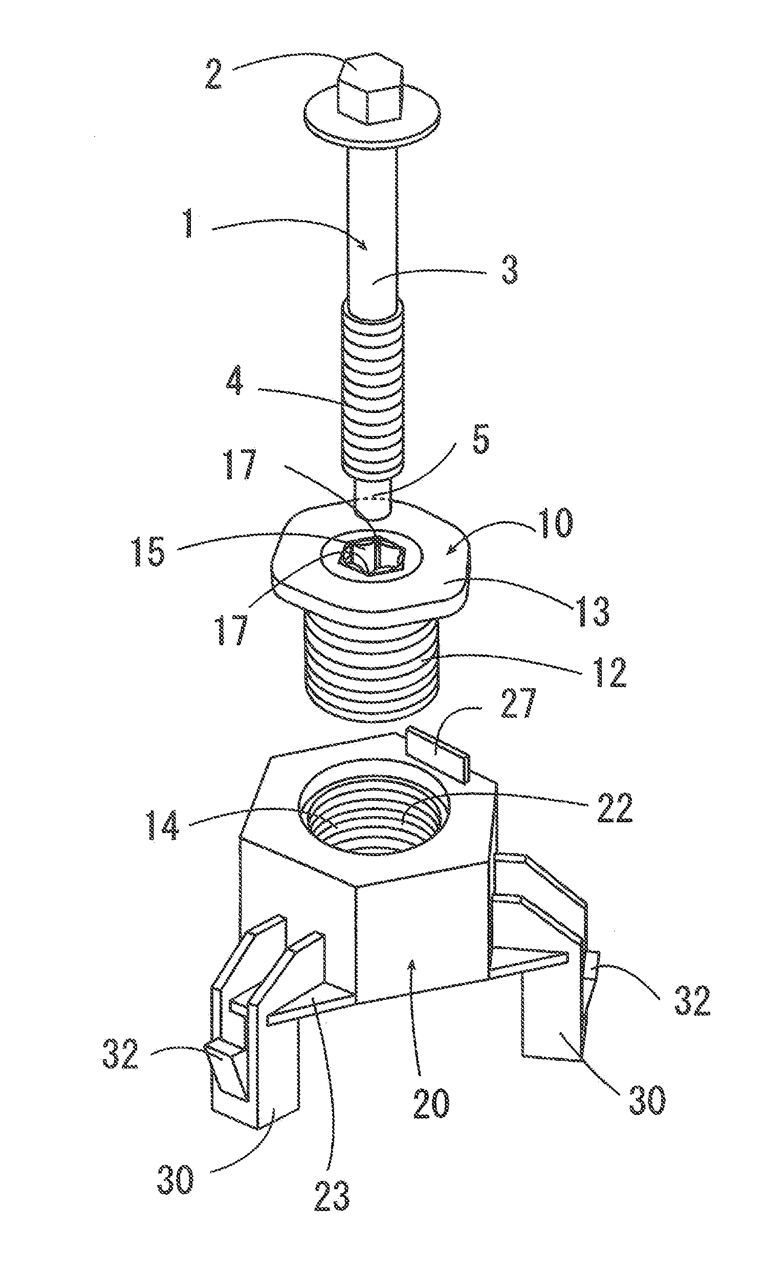
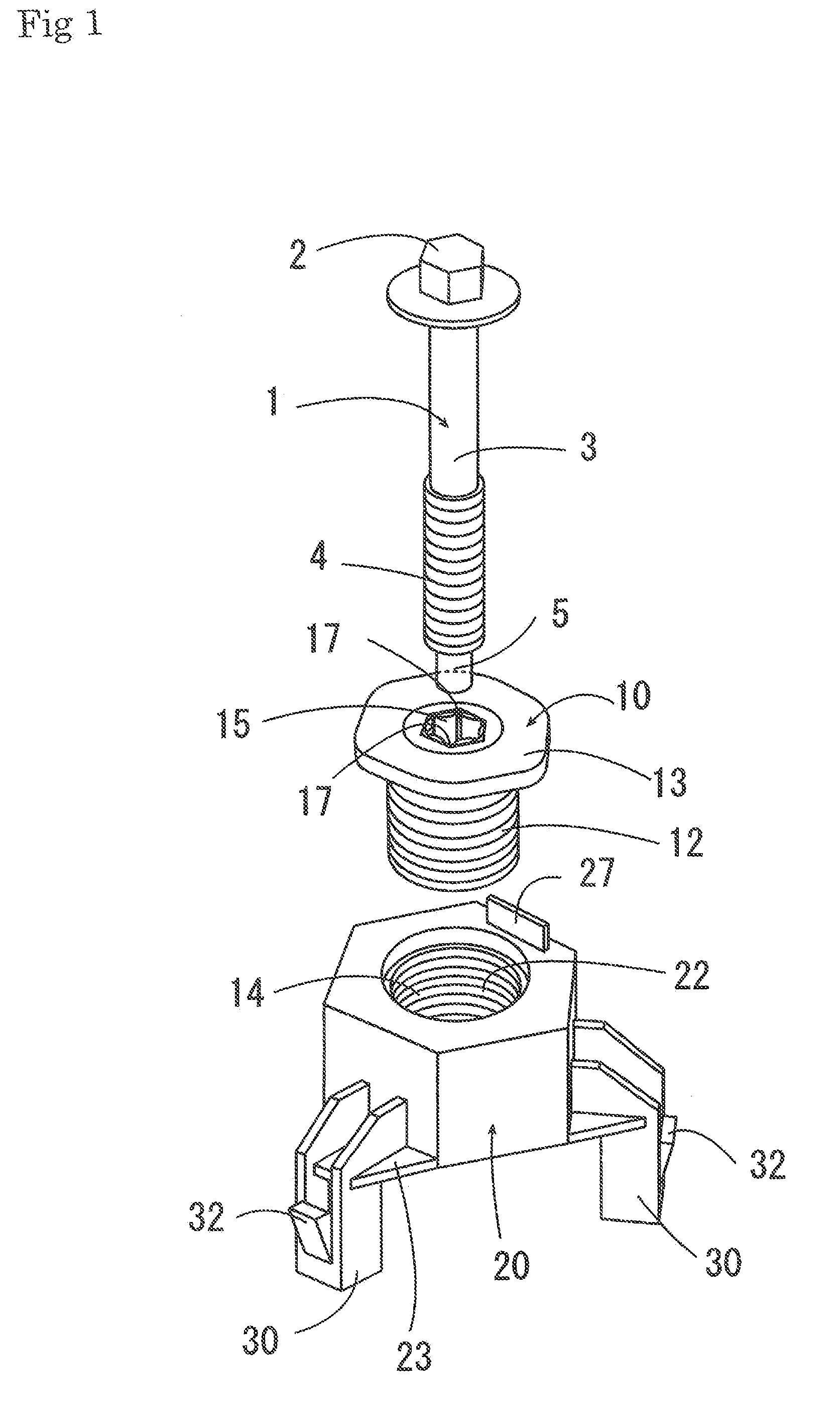
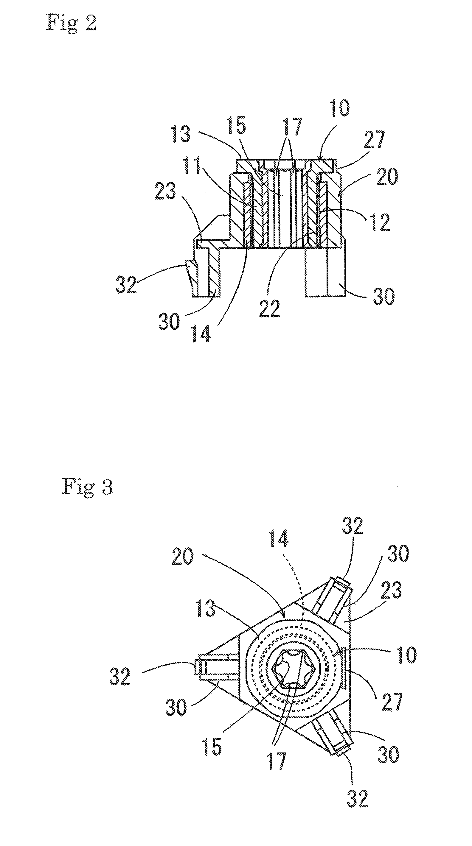
[0026]FIGS. 1 to 10 respectively show a first embodiment of the present invention. A fastening device of this embodiment is comprised of a metallic bolt 1, a metallic movable spacer 10, a sleeve 20, and a metallic nut 31. A first member 40 is formed with a bolt inserting hole 42, and the metallic nut 31 is welded to the back surface of the first member 40. The bolt 1 is comprised of a head portion 2, a columnar shaft portion 3, and a male screw portion 4 which is a positive screw formed at the top end side of the columnar shaft portion 3. As will be described later, the bolt 1 is screwed into the movable spacer 10. At the top end side of the male screw portion 4, a stick top portion 5 having a diameter smaller than the root diameter of the male screw portion 4 is formed, for making it easy to insert and screw into female screw portions of the movable spacer 10 and the nut 31.

[0027]The sleeve 20 is fixed to the surface of the bolt inserting hole 42 of the first member 40. The sleeve ...

second embodiment

[0040]In the first embodiment described above, the movable spacer 10 and the sleeve 20 are screwed with each other in a state where the movable spacer 10 is housed in the sleeve 20. In a second embodiment shown in FIG. 11, the movable spacer 10 is formed to have a diameter larger than the diameter of the sleeve 20, so that the movable spacer 10 and the sleeve 20 are screwed with each other in a state where the sleeve 20 is housed in the movable spacer 10.

[0041]The movable spacer 20 is comprised of a cylindrical portion 11, and a plate-like portion 13 provided to close an opening portion located at one side of the cylindrical portion 11. On the inner peripheral surface of the cylindrical portion 11, a female screw portion 16 of a reversal screw is formed. On the inner peripheral surface of the center hole drilled in the plate-like portion 13, an elastic body layer 15 is formed. As in the first embodiment, the elastic body layer 15 is made of synthetic resin or synthetic rubber such a...


PUM


Abstract

A fastening device, including: a sleeve 20 fixed to a first member 40; a bolt 1; and a movable spacer 10 that is engaged with a male screw portion 4 of the bolt 1 to be detachable upon receiving a transmission torque exceeding a predetermined value, and moves to a position coming into contact with a second member 50 distanced from the first member as a result of rotating while mating with the reversal screw portion 22 of the sleeve 20 upon receiving the rotational torque from the bolt 1. On the inner peripheral surface of the movable spacer 10, an elastic body layer 15 which elastically deforms when engaged with the male screw portion 4 of the bolt 1 to exhibit a torque transmitting function and a pitch deviation absorbing function is formed.

Description

BACKGROUND OF THE INVENTION[0001]1. Field of the Invention[0002]The present invention relates to a fastening device for use in fixing two separated members while keeping them spaced at their mutual distance.[0003]2. Description of the Prior Art[0004]Conventionally, in a technical field of automobiles and the like, a fastening device for fixing two separated members to each other while keeping them spaced at their mutual distance has been suggested. For example, Patent Documents 1, 2, and 3 listed below respectively disclose a fastening device, including a sleeve fixed to a first member which is one of two separated members by welding, a movable spacer that is screwed to the sleeve by a reversal screw, and a bolt formed with a male screw portion at the top end of its shaft portion that is capable of mating with the female screw portion formed on the movable spacer. The male screw portion of the bolt and the movable spacer are engaged with each other in such a manner that they can be ...

Claims


Application Information

Patent Timeline
Patent Type & Authority Applications(United States)
IPC IPC(8): F16B5/02
CPCY10T403/75F16B5/0283
Inventor ITO, SHUJIHASEGAWA, SADAYOSHI
Owner AOYAMA SEISAKUSHO CO LTD
Learn More