Power supply device

a power supply device and power supply technology, applied in the direction of cell components, electrical appliances, cell temperature control, etc., can solve the problems of reducing the life and affecting the operation of the power supply device. , to achieve the effect of reducing the temperature variation of the cooling liquid

Inactive Publication Date: 2009-03-12
TOYOTA JIDOSHA KK
View PDF1 Cites 7 Cited by
  • Summary
  • Abstract
  • Description
  • Claims
  • Application Information

AI Technical Summary

Benefits of technology

[0011]The invention provides a power supply device in whi...

Problems solved by technology

However, the gaseous cooling medium has lower heat conductivity than that of the liquid cooling medium.
Thus, the deterioration rate varies among the power storage bodies.
This decreases the lifetime of the power supply device.
However, in the power supply device in which the plurality of power storage bodies are disposed close together, the cooling liqui...

Method used


Image

  • Power supply device
  • Power supply device
  • Power supply device

Examples


Embodiment Construction

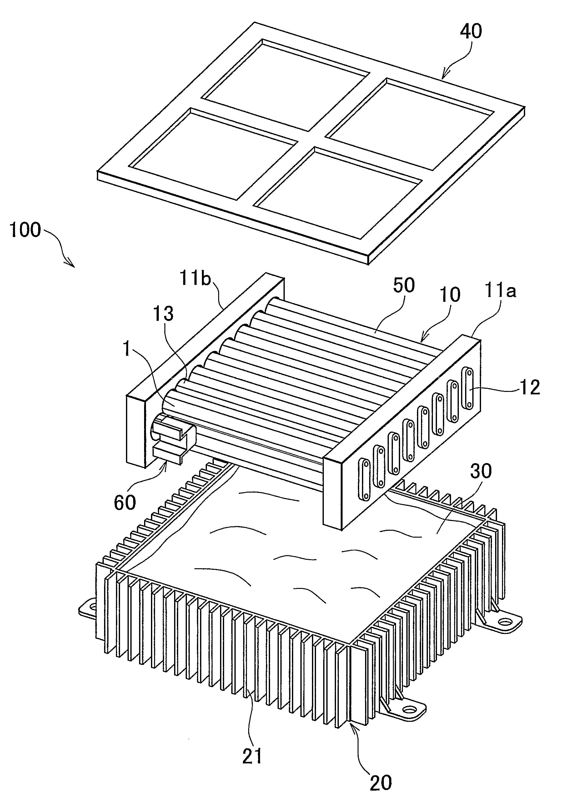
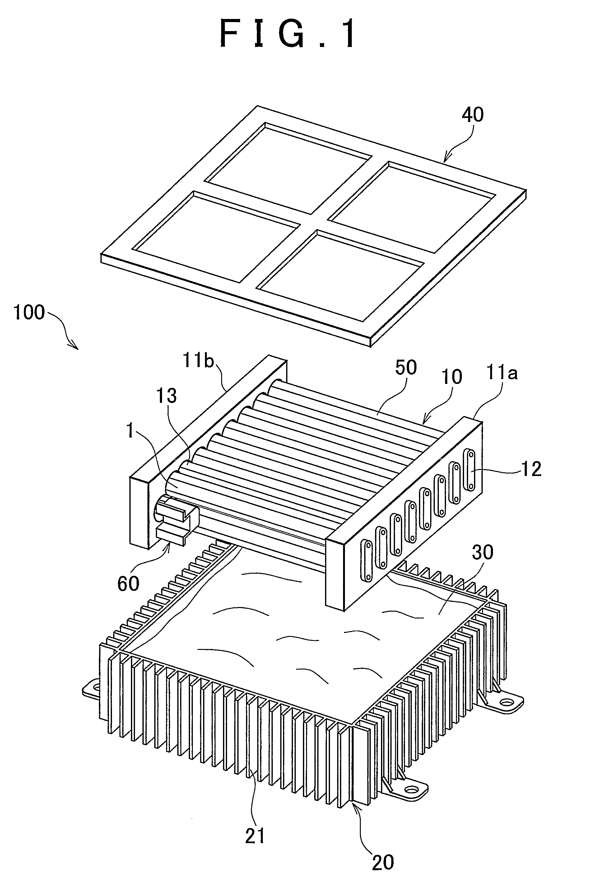
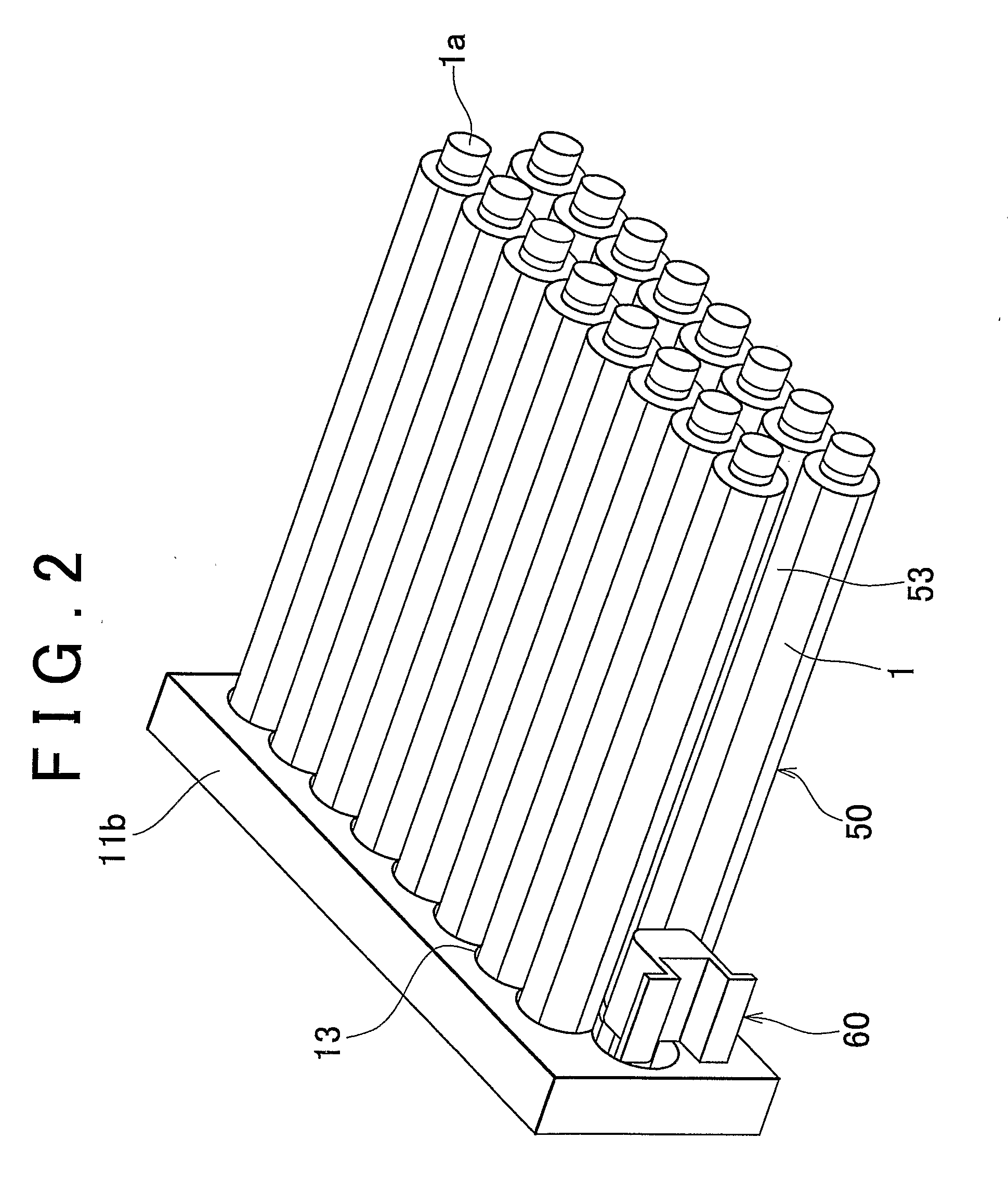
[0033]Referring to FIG. 1, A power supply device 100 according to the embodiment of the invention includes a power storage module 10, a casing 20, a cooling medium 30, a lid member 40, rotary members 50, and a motor 60. The power storage module 10 includes a plurality of cylindrical power storage bodies 1. The casing 20 houses the power storage module 10, and is filled with the cooling medium 30. The lid member 40 is placed on top of the casing 20 so as to seal the power storage module 10 and the cooling medium 30 in the casing 20. The rotary members 50 are provided to surround the respective cylindrical power storage bodies 1. The rotary members 50 are provided coaxially with the respective cylindrical power storage bodies 1 to rotate around the respective cylindrical power storage bodies 1. The motor 60 (drive means) rotates the rotary member 50.

[0034]In the first embodiment, a cooling liquid, such as cooling oil, is employed as the cooling medium 30 so that the cylindrical power ...


PUM


Abstract

A plurality of cylindrical power storage bodies are immersed in a cooling liquid filled in a power supply device. The power supply device includes: rotary members that are disposed to surround the respective cylindrical power storage bodies, and that rotate to agitate the cooling liquid around the cylindrical power storage bodies; and drive means for rotating the rotary members.

Description

BACKGROUND OF THE INVENTION[0001]1. Field of the Invention[0002]The invention relates to a power supply device, more specifically, to a cooling control for the power supply device.[0003]2. Description of the Related Art[0004]Power storage bodies, such as battery cells or capacitors, in a power supply device generate heat at the time of charging / discharging. A power storage body, such as a fuel cell or a capacitor in a power supply device, generates heat at the time of charging / discharging. Therefore, by cooling the power storage bodies using a cooling device provided in the power supply device, the temperature of the entire power supply device is controlled to make the output from the power storage bodies constant, to extend the lifetime of the power storage bodies, and to supply constant electric power.[0005]Examples of a method of cooling the power supply device (the power storage bodies) include a gaseous cooling method and a liquid cooling method. In these cooling methods, heat ...

Claims


Application Information

Patent Timeline
IPC IPC(8): H01M10/50H01M10/60H01M10/613H01M10/617H01M10/625H01M10/633H01M10/637H01M10/643H01M10/652H01M10/653H01M10/6551H01M10/6568H01M10/6569
CPCH01M10/482H01M10/5004H01M10/5075H01M10/503H01M10/5016H01M10/625H01M10/6567H01M10/643H01M10/613Y02E60/10
Inventor MURATA, TAKASHI
Owner TOYOTA JIDOSHA KK
Why Eureka
Try Eureka