Driving force controller of vehicle

Inactive Publication Date: 2009-03-12
TOYOTA JIDOSHA KK
View PDF5 Cites 15 Cited by
  • Summary
  • Abstract
  • Description
  • Claims
  • Application Information

AI Technical Summary

Benefits of technology

[0012]The present invention has been made to solve the above-described problems. An object of the invention is to provide a driving force

Problems solved by technology

Under acceleration/deceleration (transient response), however, not only an inertia torque relevant to a change of the gear ratio of the automatic transmission with respect to time but also an inertia torque relevant to a change of the wheel speed with respect to time causes the driving torque to deviate from the target value.
Further, in the case where how the gear ratio should be changed is determined based on a transmission map using the throttle opening position and the vehicle speed, the following problems arise.
In this case, there is a deviation between the target driving torque and the generated torque and thus the vehicle behavior intended by the dr

Method used


Image

  • Driving force controller of vehicle
  • Driving force controller of vehicle
  • Driving force controller of vehicle

Examples


Embodiment Construction

[0029]With reference to the drawings, embodiments of the present invention will be described hereinafter. In the following description, like components are denoted by like reference characters. They are named similarly and function similarly. Therefore, a detailed description thereof will not be repeated.

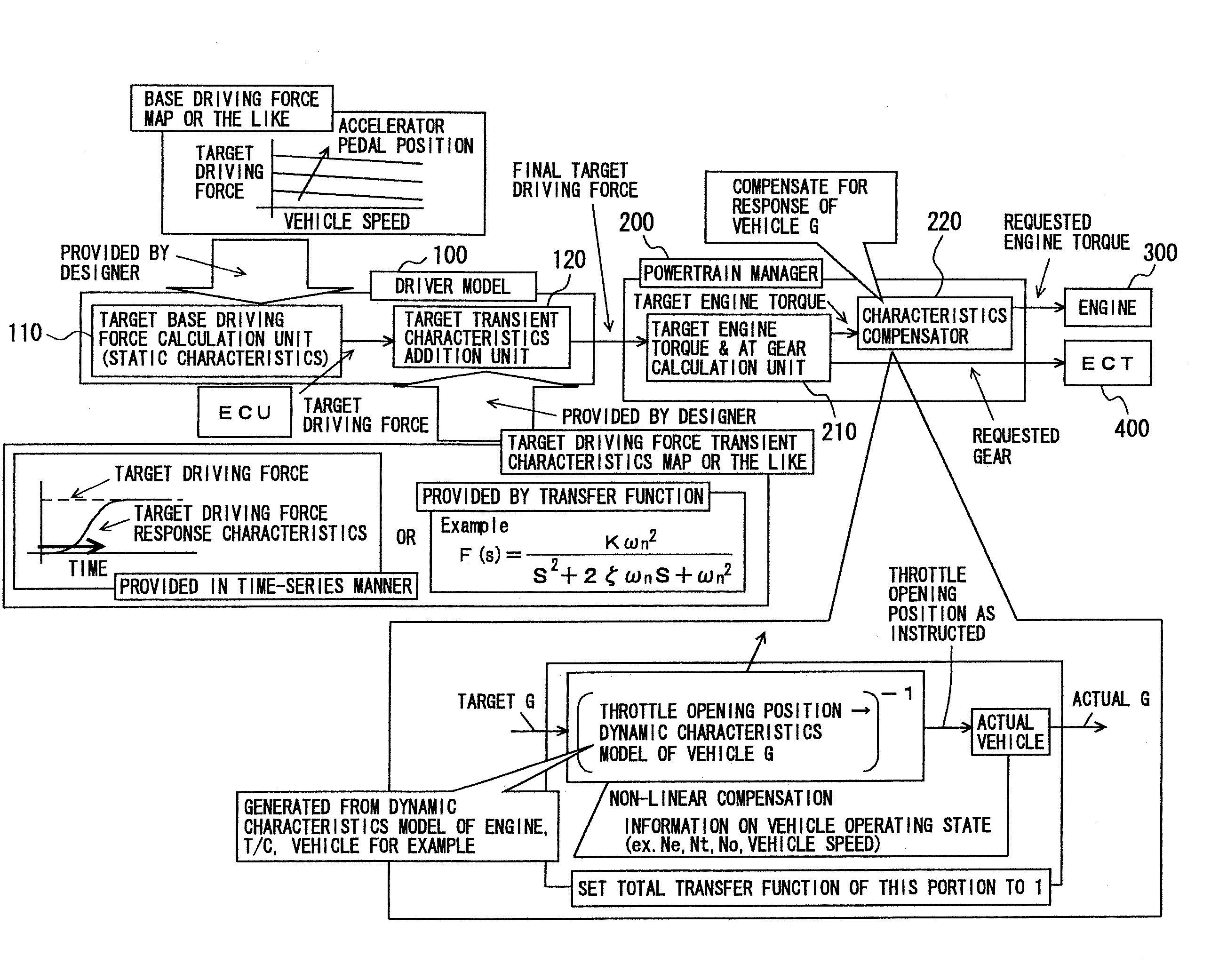
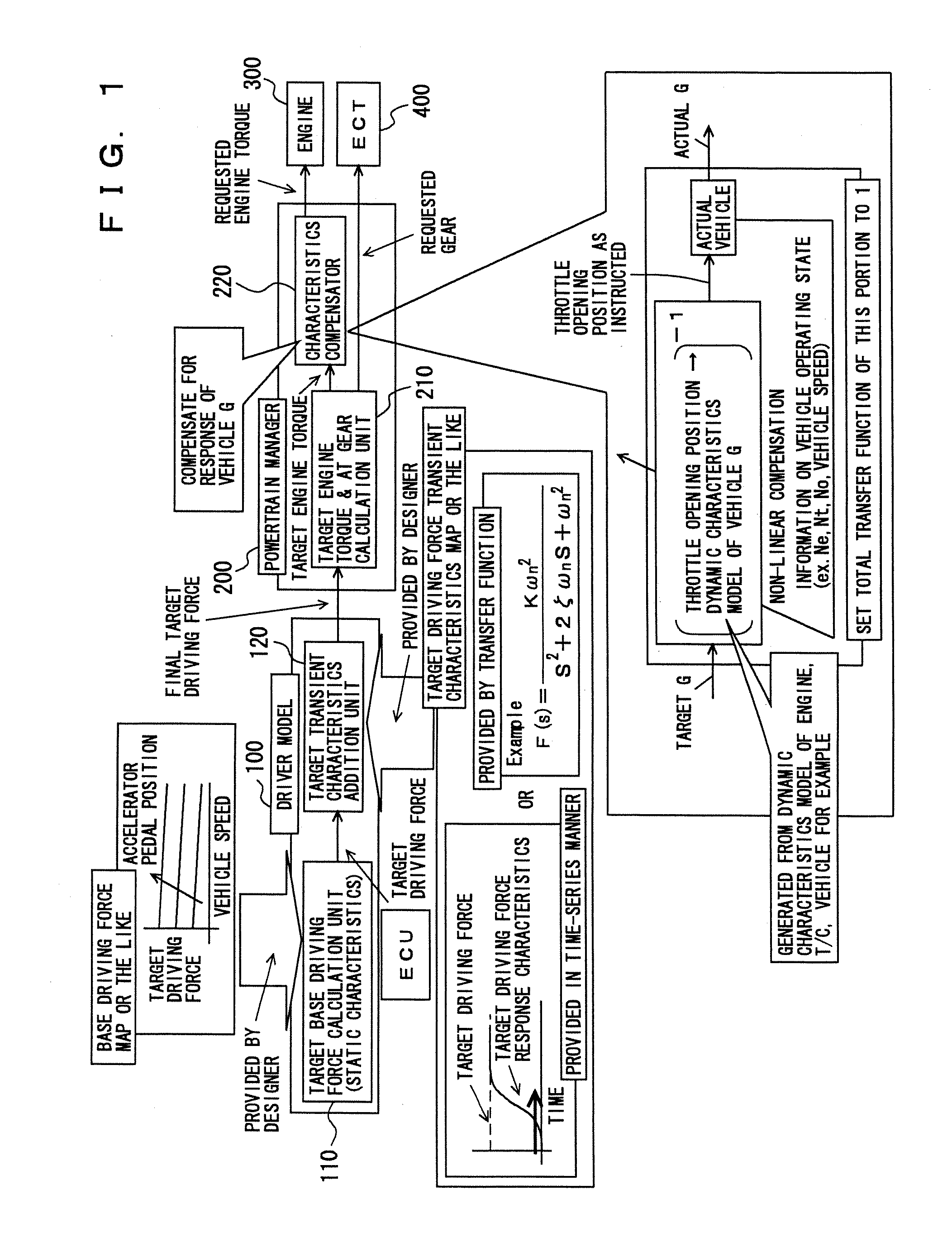
[0030]FIG. 1 shows a control block diagram of a driving force control apparatus according to the present embodiment. This driving force control apparatus is implemented by a program executed by a CPU (Central Processing Unit) included in an ECU (Electronic Control Unit) mounted on a vehicle.

[0031]As shown in FIG. 1, the driving force control apparatus finally outputs a requested engine torque to an engine 300 and outputs a requested gear to an ECT (Electronically Controlled automatic Transmission) 400. It is noted that ECT 400 may be a belt-type CVT (Continuously Variable Transmission). In this case, the output is not the requested gear but a requested gear ratio.

[0032]With referenc...


PUM


Abstract

A driving force control apparatus includes a driver model which is a functional block adjusting characteristics relevant to human senses and a powertrain manger which is a functional block adjusting vehicle's hardware characteristics. The driver model includes a target base driving force calculation unit (static characteristics) calculating a target driving force from an accelerator pedal position using a base driving force map or the like, and a target transient characteristics addition unit calculating a final target driving force from the target driving force using transient characteristics represented by a transfer function. The powertrain manager includes a target engine torque and AT gear calculation unit and a characteristics compensator compensating for response of the vehicle.

Description

TECHNICAL FIELD[0001]The present invention relates to a control apparatus for a vehicle on which mounted a powertrain that includes an engine and an automatic transmission. In particular, the invention relates to a driving force control apparatus with which a driving force corresponding to a driving force requested by a driver can be output.BACKGROUND ART[0002]To a vehicle having an engine and an automatic transmission with which an engine output torque can be controlled independently of operation of the accelerator pedal by a driver, the concept “driving force control” may be applied. According to this concept, positive and negative target driving torques, which are calculated based on for example the degree to which the accelerator pedal is operated by the driver and operating conditions of the vehicle, are accomplished by using the engine torque and the gear ratio of the automatic transmission. Such control methods as those called “driving force request type” and “driving force d...

Claims


Application Information

Patent Timeline
IPC IPC(8): B60W10/04B60W10/10B60W10/06B60W10/11F02D29/02F16H59/18F16H59/44F16H61/02F16H63/50
CPCB60W30/188B60W50/06B60W2540/10Y10T477/623F02D41/10F02D2200/606F02D2250/21F02D11/105
Inventor ASAHARA, NORIMIKONO, KATSUMI
Owner TOYOTA JIDOSHA KK
Why Eureka
Try Eureka