Geared electric motor

Inactive Publication Date: 2009-03-19
ASMO CO LTD
View PDF4 Cites 11 Cited by
  • Summary
  • Abstract
  • Description
  • Claims
  • Application Information

AI Technical Summary

Benefits of technology

[0010]The present invention addresses the above disadvantage. Thus, it is an objective of the present invention to provide a geared e

Problems solved by technology

In such a case, when the worm wheel made of resin is rotated, the worm wheel is rasped with

Method used


Image

  • Geared electric motor
  • Geared electric motor
  • Geared electric motor

Examples


first embodiment

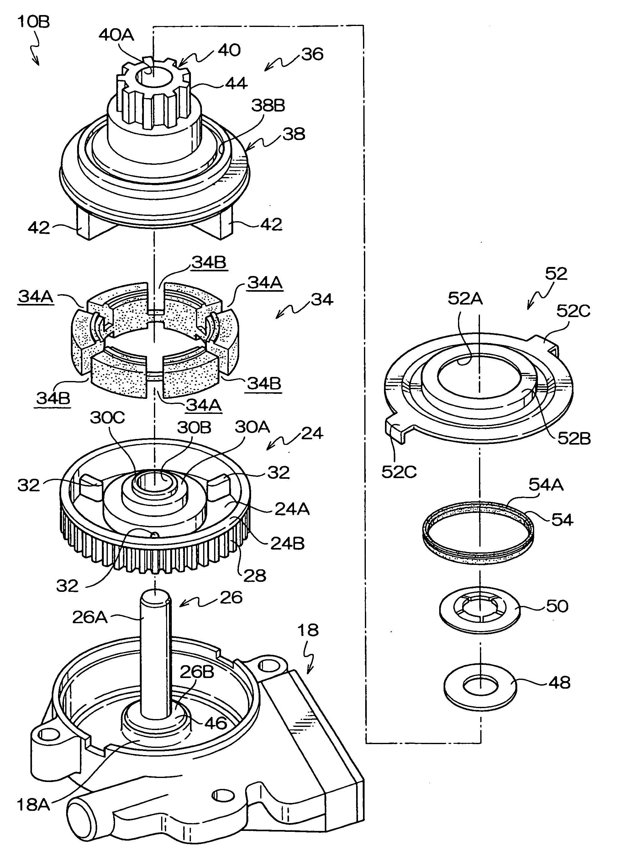
[0019]A geared electric motor (hereinafter, simply referred to as “geared motor”) 10 according to a first embodiment of the present invention will be described with reference to FIGS. 1 to 4.

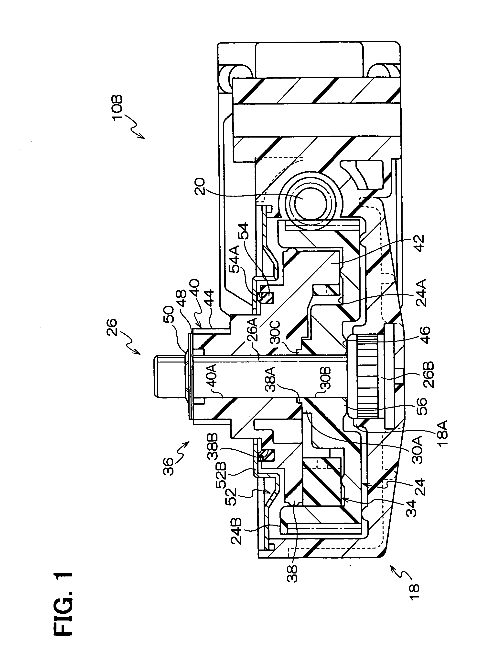
[0020]As shown in FIG. 4, the geared motor 10 includes a motor unit 10A and a speed reducing unit 10B, which are connected together. One end portion of an armature shaft 16 (rotatable shaft) of an armature 14 is rotatably supported by a bearing (not shown) in an interior of a yoke 12 of the motor unit 10A.

[0021]A distal end portion of the armature shaft 16 extends into an interior of a gear housing 18 of the speed reducing unit 10B that is connected to the yoke 12. Glass-fiber reinforced resin, which is an example of resin that improves the strength of the gear housing 18, is used as the material of the gear housing 18.

[0022]In the speed reducing unit 10B, a worm 20 is connected to the armature shaft 16. A distal end portion of the worm 20 is supported by the gear housing 18 through a bearing 22...

second embodiment

[0054]Next, a geared motor 10 according to a second embodiment of the present invention will be described with reference to FIGS. 5 and 6.

[0055]In the following description, components similar to those of the first embodiment will be indicated by the same reference numerals and will not be described further.

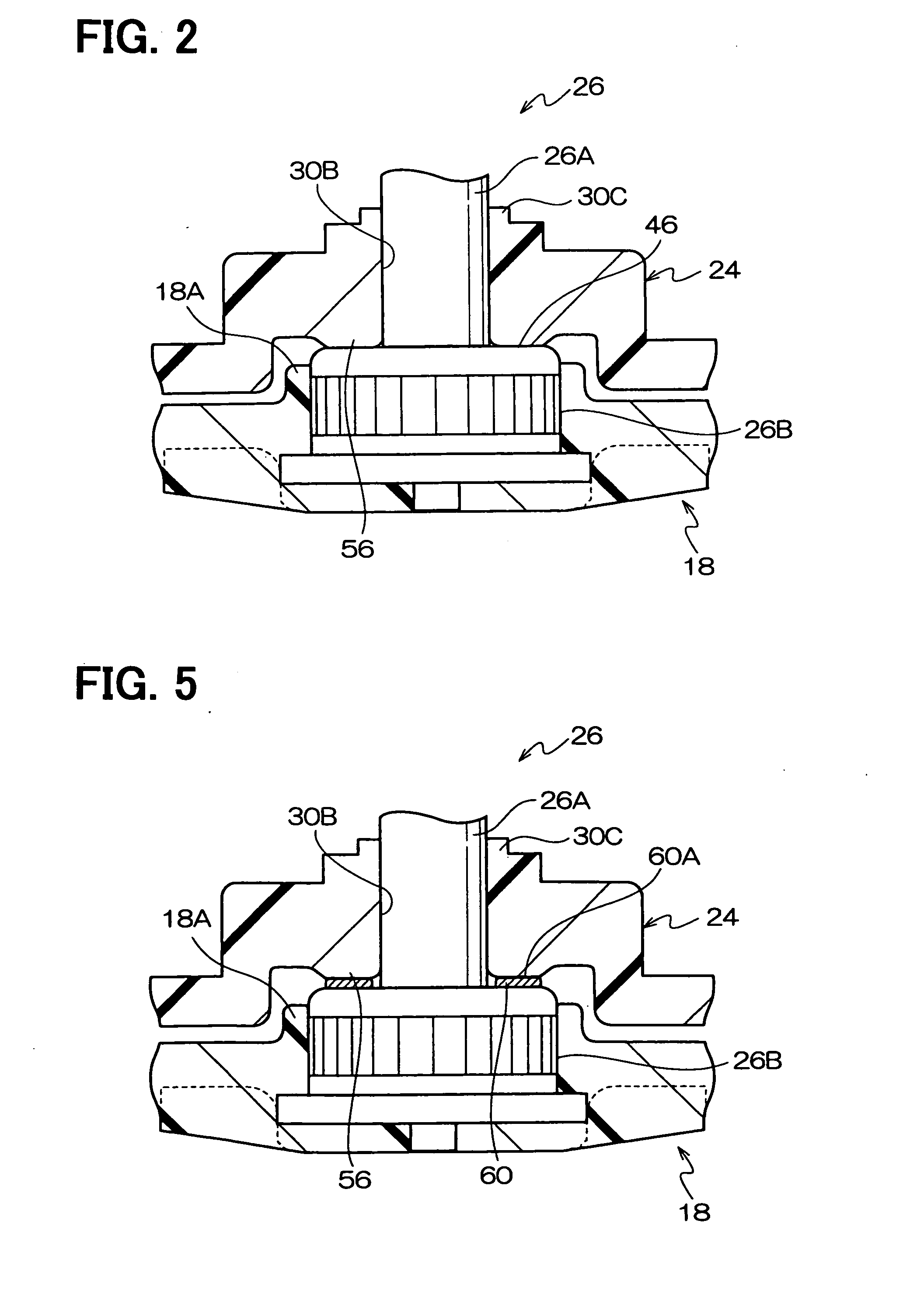
[0056]As shown in FIGS. 5 and 6, unlike the first embodiment, the top surface of the boss portion 26B is not the smooth planar surface. Instead, a plurality of elliptic projections 60 is provided on the top surface of the boss portion 26B such that the elliptic projections 60 axially project from the top surface of the boss portion 26B and radially extend in the normal direction in the plane of the top surface of the boss portion 26B. The elliptic projections 60 are arranged one after another in the circumferential direction generally at equal intervals. Furthermore, top surfaces of the projections 60 form slidably engaging surfaces 60A.

[0057]In the case where the slidably engagi...


PUM

PropertyMeasurementUnit
Diameteraaaaaaaaaa

Abstract

A housing is made of resin and receives a worm. A worm wheel is made of resin and is received in the housing to mesh with the worm. A support shaft includes a shaft portion and a boss portion. The shaft portion rotatably supports the worm wheel. The boss portion is made of metal and is fixed to the housing. The boss portion holds the shaft portion and includes a slidably engaging surface that slidably engages the worm wheel.

Description

CROSS REFERENCE TO RELATED APPLICATION[0001]This application is based on and incorporates herein by reference Japanese Patent Application No. 2007-239073 filed on Sep. 14, 2007.BACKGROUND OF THE INVENTION[0002]1. Field of the Invention[0003]The present invention relates to a geared electric motor.[0004]2. Description of Related Art[0005]A geared electric motor is used as, for example, a drive source of a power window apparatus that drives a window glass of a door of a vehicle to open and close the same, or a drive source of a sunroof apparatus that drives a sunroof panel of the vehicle to open and close the same.[0006]Japanese Unexamined Patent Publication No. H08-84456 discloses a geared electric motor, in which a worm wheel is meshed with a worm provided in a rotatable shaft of an armature to reduce a rotational speed of the rotatable shaft through the worm wheel. The rotation at the reduced rotational speed is transmitted from the worm wheel to an output shaft of the geared elect...

Claims


Application Information

Patent Timeline
IPC IPC(8): F16H1/16
CPCE05Y2900/55F16H1/16F16H57/021F16H57/039E05F15/697H02K7/116H02K7/1166Y10T74/19828F16H2057/0325
Inventor NAKAGAWA, ATSUSHI
Owner ASMO CO LTD
Why Eureka
Try Eureka