
Dispenser

Active Publication Date: 2009-03-19
YONWOO CO LTD
View PDF5 Cites 30 Cited by
  • Summary
  • Abstract
  • Description
  • Claims
  • Application Information

AI Technical Summary

Benefits of technology

[0006]Accordingly, the present invention has been made keeping in mind the above problems occurring in the prior art, and an object of the present invention is to provide a dispenser which can conveniently discharge contents, adjust the amount of contents that is discharged, and prevent the loss of elements.Technical Solution
[0008]In the dispenser according to the present invention, the method of discharging contents is convenient, and the amount of contents that is discharged can be easily adjusted. As well, the present invention can prevent the loss of parts.

Problems solved by technology

Furthermore, it is very difficult for the user to control the distance that the button 20 is moved when pushing the button 20.
As such, the conventional dispenser is problematic in that it is difficult to adjust the amount of contents that is discharged.

Method used


Image

  • Dispenser
  • Dispenser
  • Dispenser

Examples


Embodiment Construction

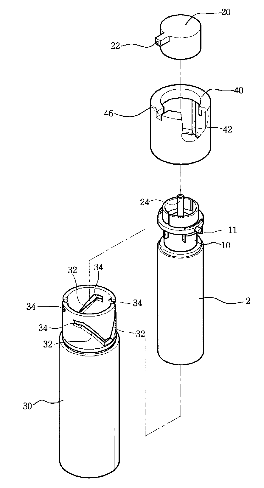
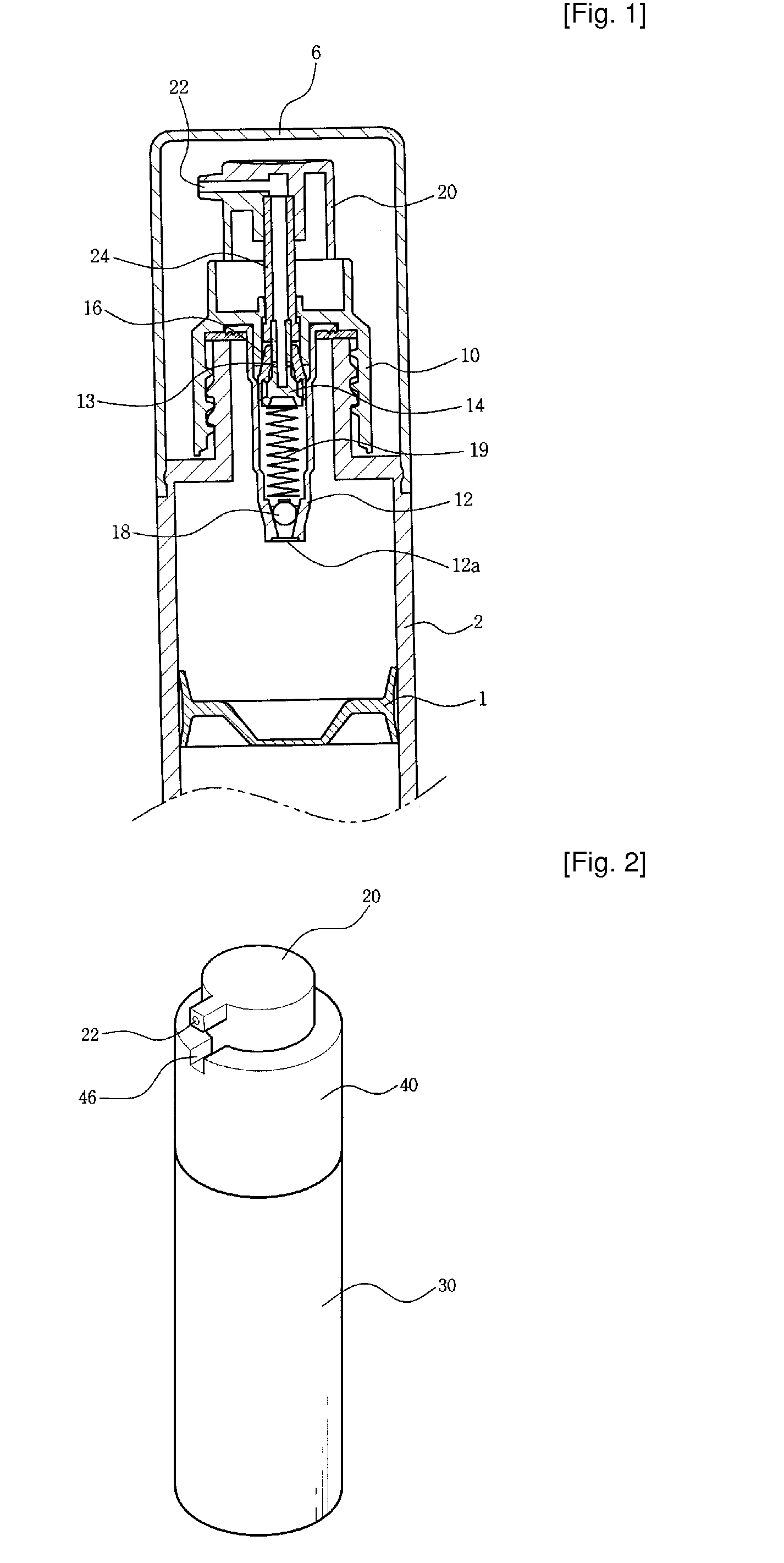
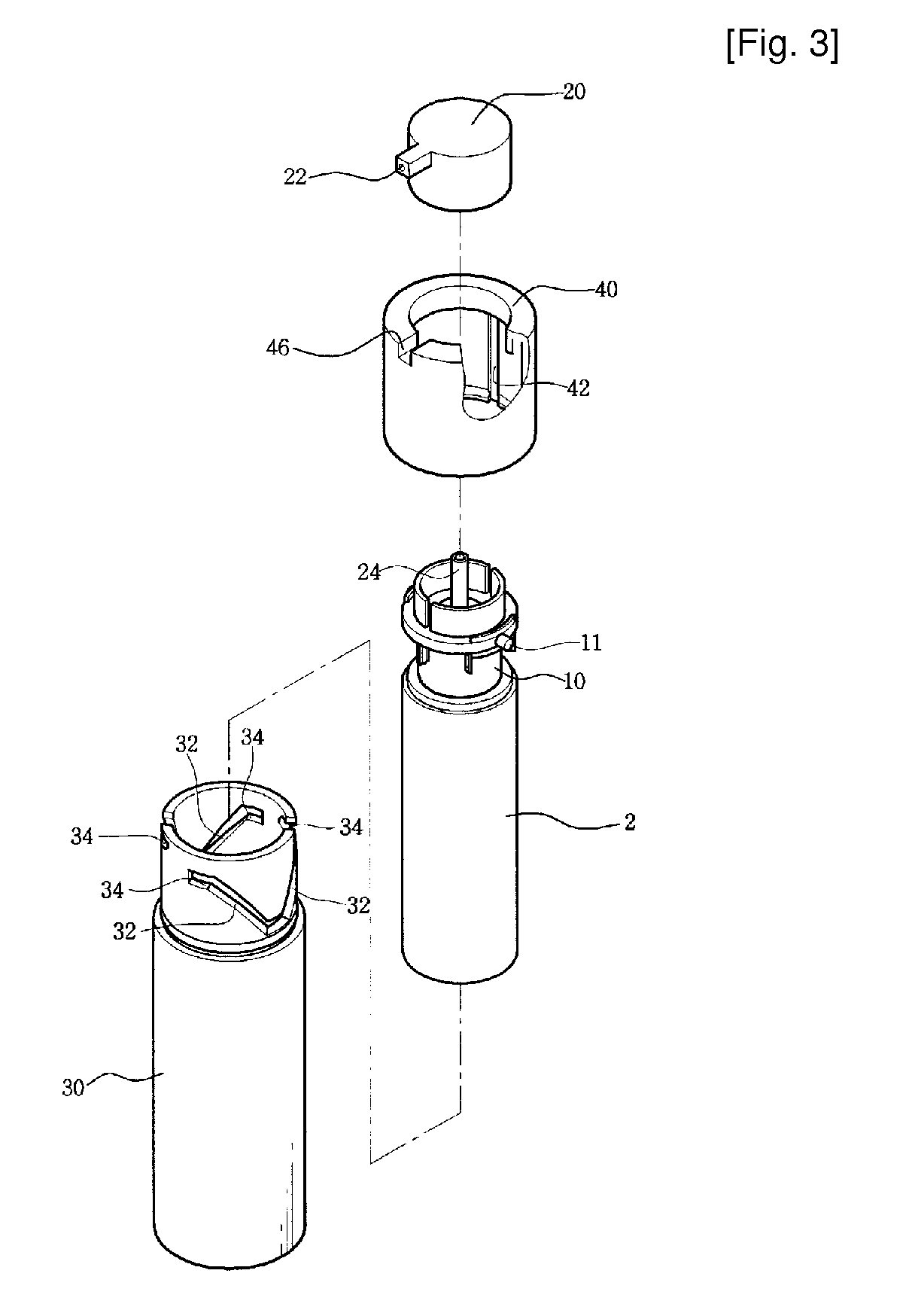
[0014]In order to accomplish the above object, the present invention provides a dispenser, comprising a container (2) to store contents therein, a dispenser cap (10) coupled to an upper end of the container (2) to pump the contents, a button (20) coupled to an upper end of the dispenser cap (10) so as to be movable in a longitudinal direction, with a nozzle (22) provided at a predetermined position in the button (20), and an outer casing (30) surrounding the container (2), wherein a plurality of guide slots (32), upper ends of which differ in height from each other, and lower ends of which are coupled to each other, is formed in an upper end of the outer casing (30), with a horizontal extension slot (34) extending from an upper end of each of the plurality of guide slots (32), a hollow rotating body (40) is rotatably coupled to the upper end of the outer casing (30), with a guide groove (42) formed in a circumferential inner surface of the hollow rotating body (40) in a longitudinal...


PUM


Abstract

The present invention provides a dispenser, which includes a container (2), a dispenser cap (10), a button (20) and an outer casing (30). Particularly, in the present invention, guide slots (32), upper ends of which differ in height from each other, are formed in the outer casing. A horizontal extension slot (34) extends from an upper end of each guide slot. A hollow rotating body (40) is rotatably coupled to the outer casing. A guide groove (42) is formed in the hollow rotating body, and a guide protrusion (11) is provided on the outer surface of the dispenser cap. Thus, when the hollow rotating body is rotated, the guide protrusion is moved upwards along the corresponding guide slot and the guide groove and is inserted into the corresponding horizontal extension groove, thus adjusting the distance to which the button is movable downwards, thereby adjusting the amount of contents that is discharged.

Description

TECHNICAL FIELD[0001]The present invention relates, in general, to dispensers and, more particularly, to a dispenser which is constructed such that the amount of contents that is discharged can be easily adjusted, and such that it is convenient to use.BACKGROUND ART[0002]Generally, dispensers, which discharge a predetermined amount of liquid- or gel-phase contents, such as a cosmetic, at one time using pneumatic pressure, are classified into a dip tube type dispenser, in which some of the contents is drawn into a dip tube and is discharged from casing while the same volume of air is drawn into the casing, and an airless type dispenser, in which a piston is moved upwards by vacuum pressure and contents are thus pushed upwards.[0003]FIG. 1 shows an example of a conventional airless type dispenser. As shown in the drawing, the conventional airless type dispenser includes a container 2, which stores contents therein, a dispenser cap 10, which is coupled to the upper end of the container...

Claims


Application Information

Patent Timeline
IPC IPC(8): G01F11/00
CPCB05B11/0027B05B11/0037B05B11/3059B05B11/3008B05B11/0048B05B11/0038B05B11/1008B05B11/028B05B11/1059B65D83/00B65D47/00
Inventor KI, JOONG HYUN
Owner YONWOO CO LTD
Features
  • Generate Ideas
  • Intellectual Property
  • Life Sciences
  • Materials
  • Tech Scout
  • Unparalleled Data Quality
  • Higher Quality Content
  • 60% Fewer Hallucinations
Learn More