Al technical title is built by PatSnap Al team. It summarizes the technical point description of the patent document.
a magnetic flakes and anisotropic technology, applied in the field of thin pigment flakes, can solve the problem of additional cos
Active Publication Date: 2009-03-19
VIAVI SOLUTIONS INC
View PDF52 Cites 151 Cited by
Summary
Abstract
Description
Claims
Application Information
AI Technical Summary
This helps you quickly interpret patents by identifying the three key elements:
Problems solved by technology
Method used
Benefits of technology
[0013]The ribbons of three or more flakes may be used as a security feature on documents, banknotes, etc. The instant invention provides a method of authentication of an object including the step of identifying a ribbon in a flake-containing coating. In one embodiment, the flakes forming the ribbon have a binary grating thereon, which provides a pattern of reflected light beams used for authentication of the object.
Problems solved by technology
An increase of pigment concentration can improve the reflectivity of the printed images and paint coatings, but is associated with additional cost, with thicker coatings, and with flakes overlapping one another preventing them from lying flat against the substrate.
Method used
Image
Click on the blue label to locate the original text in one second.
Reading with bidirectional positioning of images and text.
Examples
Embodiment Construction
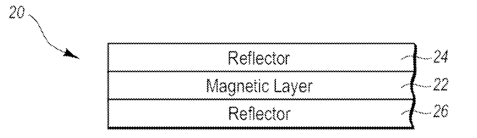
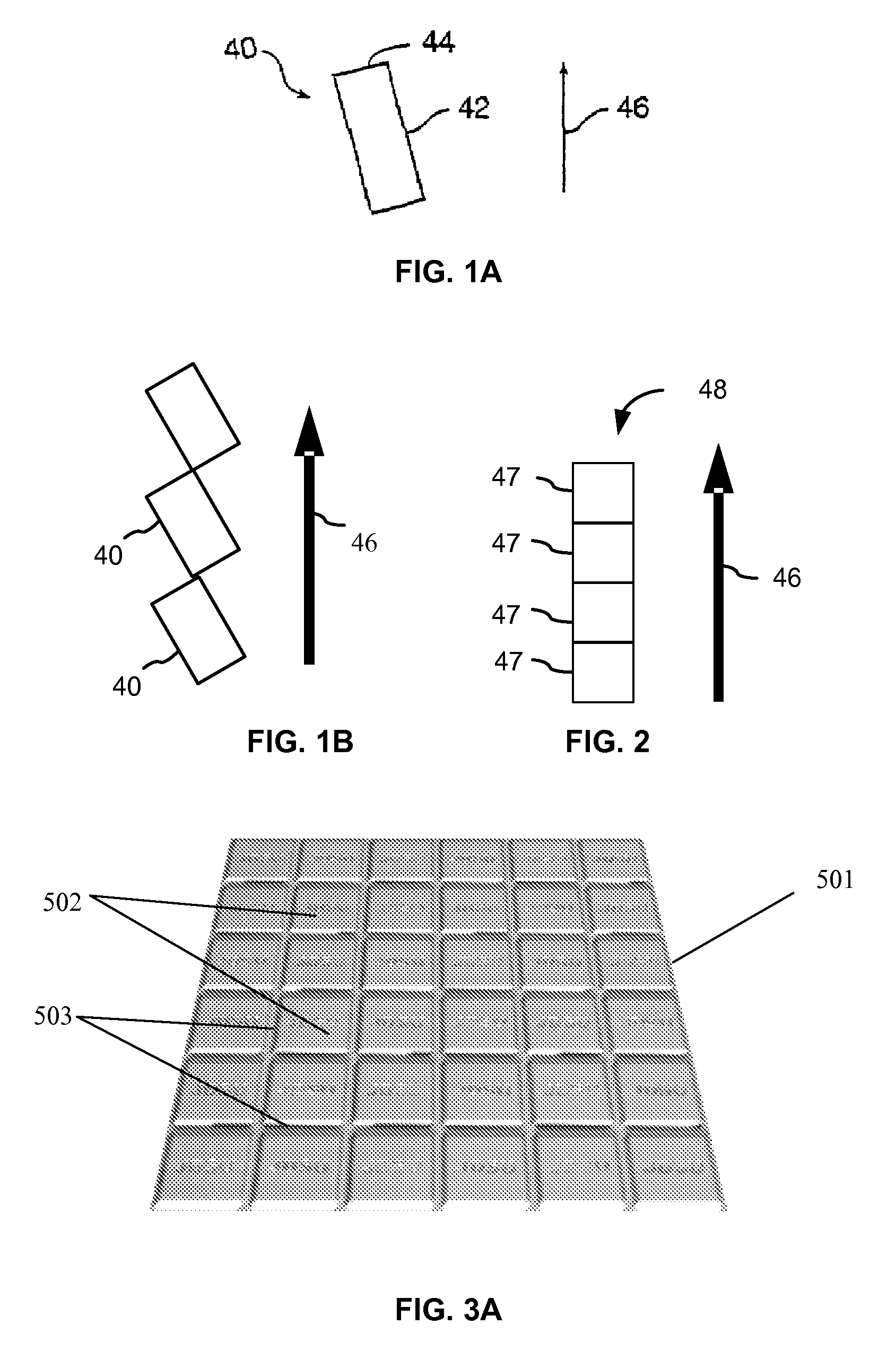
[0039]A magnetic flake is a pigment flake that includes a magnetic material. It is known that a square-shaped magnetic flake without a grating has its easy magnetic axis, i.e. a direction of its magnetic moment, along a diagonal of the square, and North and South magnetic poles—at opposite corners of the square. FIG. 1A, which is a copy of FIG. 2a from U.S. Pat. No. 7,300,695 issued Nov. 27, 2007, to Argoitia et al., illustrates a rectangular magnetic flake 40 with sides 42 and 44 in a liquid medium and under influence of a magnetic field. The flake 40 orients so as to have a diagonal along the direction of the applied magnetic field 46. North and South magnetic poles of different flakes attract and flakes may form corner-to-corner chains such as shown in FIG. 1B.
[0040]It has been unexpectedly discovered that, when dispersed in a liquid carrier and impacted by a magnetic field, square-shaped, non-grated magnetic flakes of a particular kind form different structures, namely ribbons. ...
PUM
Property
Measurement
Unit
reflectivity
aaaaa
aaaaa
angle
aaaaa
aaaaa
thickness
aaaaa
aaaaa
Abstract
The invention relates to anisotropic, reflective, magnetic flakes. In a liquid carrier and under influence of an external magnetic field, the flakes attract to one another side-by-side and form ribbons which provide higher reflectivity to a coating and may be used as a security feature for authentication of an object.
Description
CROSS-REFERENCE TO RELATED APPLICATIONS[0001]The present invention claims priority from U.S. Provisional Application Ser. No. 60 / 973,546 filed Sep. 19, 2007, which is incorporated herein by reference.[0002]This application is a continuation-in-part of U.S. patent application Ser. No. 12 / 051,164, filed Mar. 19, 2008, which claims priority from U.S. Provisional Application Ser. No. 60 / 919,204, filed on Mar. 21, 2007, which is incorporated herein by reference.[0003]This application is a continuation-in-part of U.S. patent application Ser. No. 12 / 107,152, filed Apr. 22, 2008, which claims priority from U.S. Provisional Application Ser. No. 60 / 913,423, filed Apr. 23, 2007, which is incorporated herein by reference.[0004]This application is a continuation-in-part of U.S. patent application Ser. No. 11 / 461,870, filed Aug. 2, 2006, which is incorporated herein by reference for all purposes. The 11 / 461,870 is a continuation-in-part of U.S. patent application Ser. No. 11 / 028,819, filed on Jan...
Claims
Application Information
Patent Timeline
Application Date:The date an application was filed.
Publication Date:The date a patent or application was officially published.
First Publication Date:The earliest publication date of a patent with the same application number.
Issue Date:Publication date of the patent grant document.
PCT Entry Date:The Entry date of PCT National Phase.
Estimated Expiry Date:The statutory expiry date of a patent right according to the Patent Law, and it is the longest term of protection that the patent right can achieve without the termination of the patent right due to other reasons(Term extension factor has been taken into account ).
Invalid Date:Actual expiry date is based on effective date or publication date of legal transaction data of invalid patent.
Patent Type & Authority Applications(United States)