Chuck Body for a Chuck, Chuck and Method for Determining a Clamping Force on Such a Chuck

a technology of chuck body and chuck body, which is applied in the direction of chucks, apparatus for force/torque/work measurement, and using mechanical means, etc., can solve the problems of reducing the clamping force of the workpi

Active Publication Date: 2009-03-19
HAINBUUFU GMBH SHUPANENDE TEHINIKU
View PDF10 Cites 19 Cited by
  • Summary
  • Abstract
  • Description
  • Claims
  • Application Information

AI Technical Summary

Benefits of technology

[0009]In a further development of the invention the deformation sensor is placed on the outer surface or outside of the basic body so as to be accessible from the outside. This allows an easy fitting of the deformation sensor and provides good accessibility for fault detection or an optionally necessary replacement. In addition, for maintaining or repairing the deformation sensor there is no need to dismantle the chuck, so that in the case of a fault a rapid and therefore inexpensive solution is available, which plays a positive part in connection with the usability of the chuck.
[0012]In a further development of the invention with the deformation sensor is associated an information transmission device, which is designed for a wireless signal transmission, preferably via a radio link, from deformation sensor to a receiver means. Thus, the deformation sensor measurement signal can be transmitted in uncomplicated manner and without complicated cabling to a receiver means, which is in particular fitted to the machine tool. As a result of the wireless transmission of signals the chuck body can be easily replaced and stored in the same way as a known chuck body.
[0015]In a further development of the invention the information transmission device is in the form of an RFID transponder for a data transfer via an inductive near field or an electromagnetic far field. An RFID transponder is a device which with the aid of so-called radio frequency identification permits a transmission of data such as measurement signals. For this purpose an inductive near field or an electromagnet far field is necessary and is made available by a transmitting device such as the machine tool. Advantageously the field is generated by a device separate from the machine tool. It can for example function independently of the machine, which facilitates the usability of chucks equipped with RFID transponders and / or with other signal transmission devices.
[0019]According to another aspect of the invention a chuck with a chuck body having at least one of the aforementioned features and with a clamping head receivable in the chuck body is provided. The clamping head has several clamping jaws spaced from one another by separation slots and which can be interconnected in relatively movable manner by means of elastic connecting elements and provided for the fixing of a workpiece. Such a chuck ensures a cycle-independent, as needed maintenance of the clamping head and chuck body as a function of the actual clamping force. The chuck together with a receiver means can make available information on the workpiece clamping force derived from the chuck body deformation and therefore information on the chuck maintenance state, without it being necessary to dismantle the clamping head from the chuck body. The invention is generally usable in the case of chucks and with particular advantage with an axial tension chuck.
[0021]This method determines a clamping force present during chuck rotation and vital for workpiece machining. This clamping force can differ significantly from the clamping force when stationary and this can in particular result from the centrifugal forces which occur. In addition, setting and sliding processes between clamping head and chuck body as a result of rotation can occur and can bring about an at least partial compensation of the centrifugal force-dependent clamping force reduction. The method makes it possible to determine the actual clamping force on the workpiece.
[0025]In a further development of the invention there is a regulation or control of an axial tensile force exerted on the chuck as a function of the circumferentially determined chuck body deformation, particularly as a function of the clamping force efficiency of the chuck. This allows an at least partial compensation of the clamping force reduction occurring as a function of the chuck maintenance state by increasing the tensile force exerted by the tension tube.

Problems solved by technology

It is possible that a chuck maintenance was already overdue as a result of unfavourable ambient conditions and the final machining cycles were carried out with a clamping force below the minimum clamping force.
A considerable influence on the need for maintenance of a chuck is exerted by contamination and high temperatures, which as a result of dirt particles and / or transformation processes in the lubricant can lead to a rapid increase in the friction between the clamping head and chuck body and consequently have a negative influence on the clamping force on the workpiece.

Method used


Image

  • Chuck Body for a Chuck, Chuck and Method for Determining a Clamping Force on Such a Chuck
  • Chuck Body for a Chuck, Chuck and Method for Determining a Clamping Force on Such a Chuck
  • Chuck Body for a Chuck, Chuck and Method for Determining a Clamping Force on Such a Chuck

Examples


Embodiment Construction

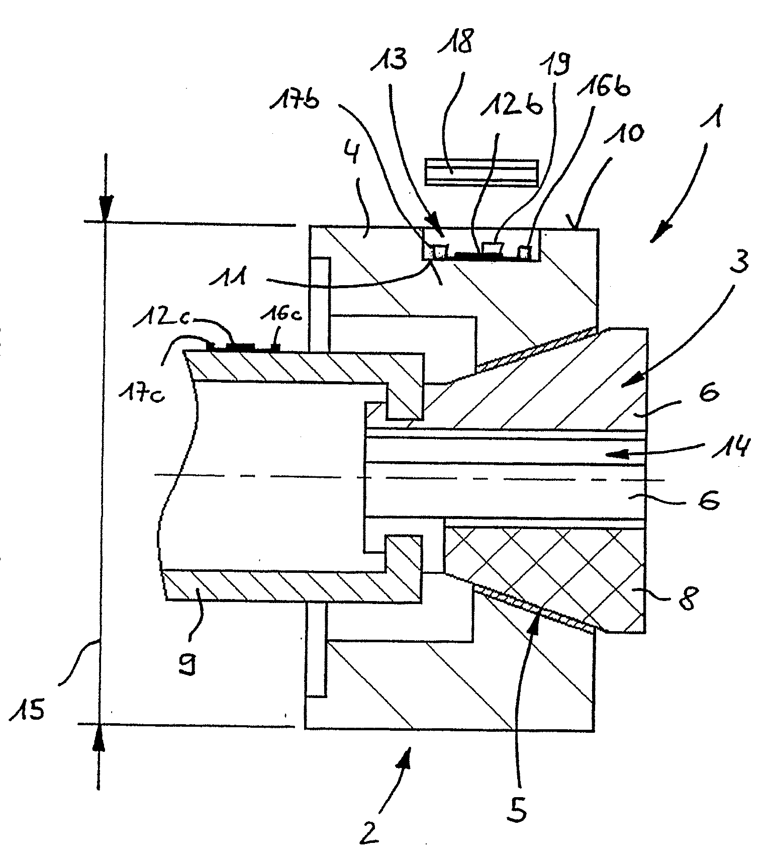
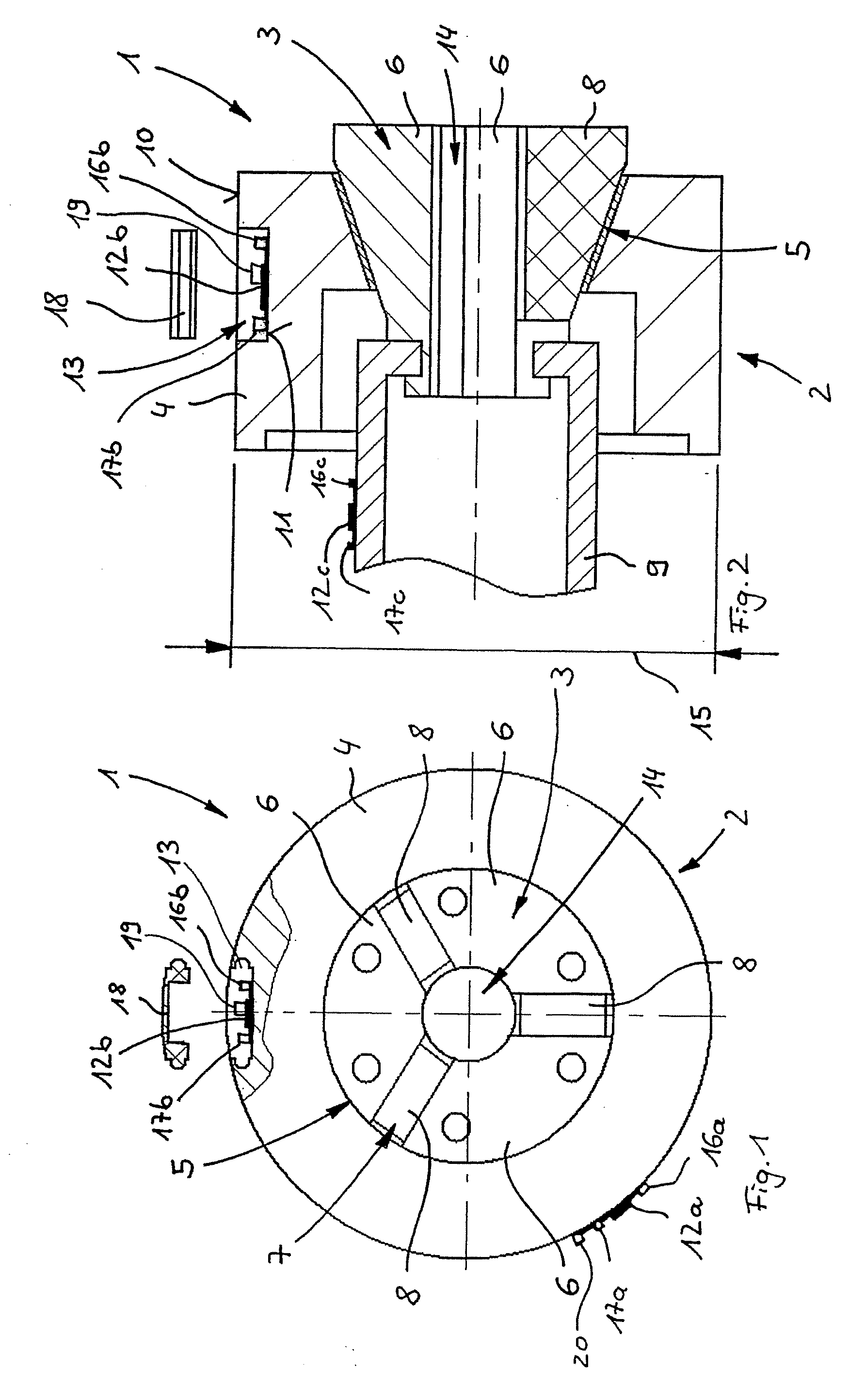
[0032]FIGS. 1 and 2 show a chuck 1 for clamping a preferably cylindrically designed workpiece in the manner of a collet. The chuck 1 has a substantially rotationally symmetrical basic body 4 forming an essential part of chuck body 2. On the basic body 4 is provided a cone portion-shaped reception opening 5 for a force-transferring reception of a clamping head 3. The clamping head 3 is constructed from three clamping jaws 6 spaced from one another by separation slots 7, which are in some areas bridged by elastic connecting elements 8, which interconnect the clamping jaws 6 in self substance, relatively movable manner. On a tapered end portion of the clamping head 3 the clamping jaws 6 are provided with a circumferential groove in which can engage a tension tube 9, which forms part of a not shown machine spindle and which can exert a tensile force on the chuck 3.

[0033]On an outer surface 10 is provided a deformation sensor 12a. A pocket-like depression 13 contains a further deformatio...


PUM

PropertyMeasurementUnit
electrical resistanceaaaaaaaaaa
electrical energyaaaaaaaaaa
rotary movementaaaaaaaaaa

Abstract

A chuck body for a clamping chuck for clamping a workpiece has a substantially rotationally symmetrically formed basic body, provided on which is a receiving opening, which is formed as a portion of a cone and is formed for receiving a clamping head in such a way as to transmit force. Attached to the basic body is a deformation sensor, for example as a strain gauge, which is intended and designed for determining a deformation of the basic body in a circumferential direction. In this way, the condition and state of wear of the clamping chuck can be determined.

Description

FIELD OF APPLICATION AND PRIOR ART[0001]The invention relates to a chuck body for a chuck for clamping a workpiece, having a substantially rotationally symmetrically designed basic body on which is provided a cone portion-shaped receiving opening designed for a force-transferring reception of a clamping head, as well as a chuck equipped with such a chuck body and a method for determining a clamping force on a chuck.[0002]U.S. Pat. No. 6,908,086 describes a chuck with a chuck body having an internal conical surface for receiving a clamping head. The clamping head has an at least segmentally conical outer contour which is matched to the chuck body and is subdivided by means of several separation slots into individual clamping jaws, which are coupled together in relatively movable manner by elastic connecting elements. By exerting an axially directed tensile force on the clamping head the latter can be fixed in the chuck body and as a result of the tensile force exerted there is a radi...

Claims


Application Information

Patent Timeline
Patent Type & Authority Applications(United States)
IPC IPC(8): B23B31/12G01L3/00
CPCB23B31/207Y10T279/17641B23Q17/005B23B2260/128B23B31/2073
Inventor WELLER, HANS-MICHAELMANDARELLO, ATTILIO
Owner HAINBUUFU GMBH SHUPANENDE TEHINIKU
Why Eureka
Try Eureka