

Laminated balun transformer
a balun transformer and laminate technology, applied in the field of laminated balun transformers, can solve the problems of inability to adapt to different impedances, and inability to use existing balun transformers for lines having various impedances
- Summary
- Abstract
- Description
- Claims
- Application Information
AI Technical Summary
Benefits of technology
Problems solved by technology
Method used
Image

Examples
first preferred embodiment
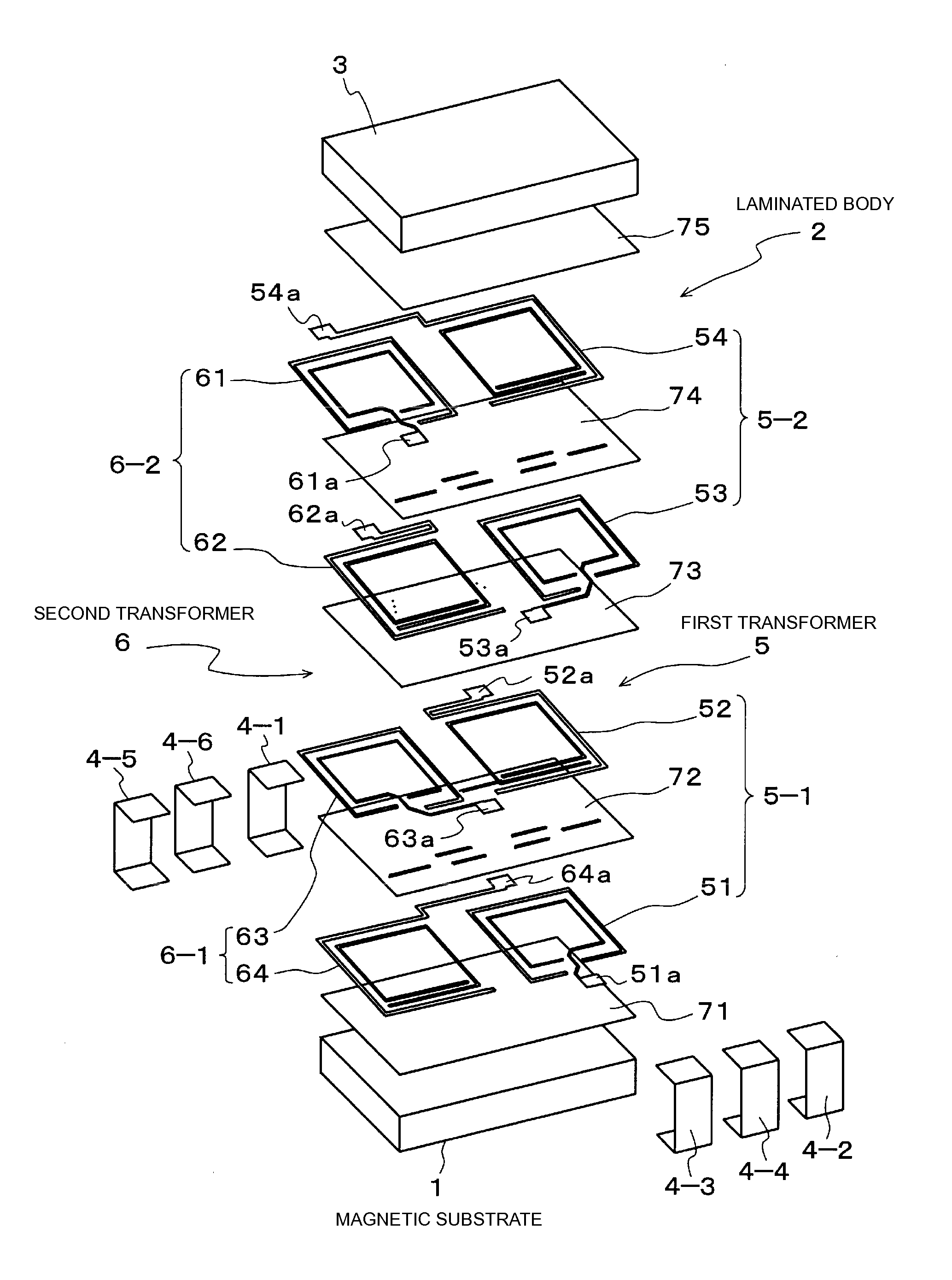
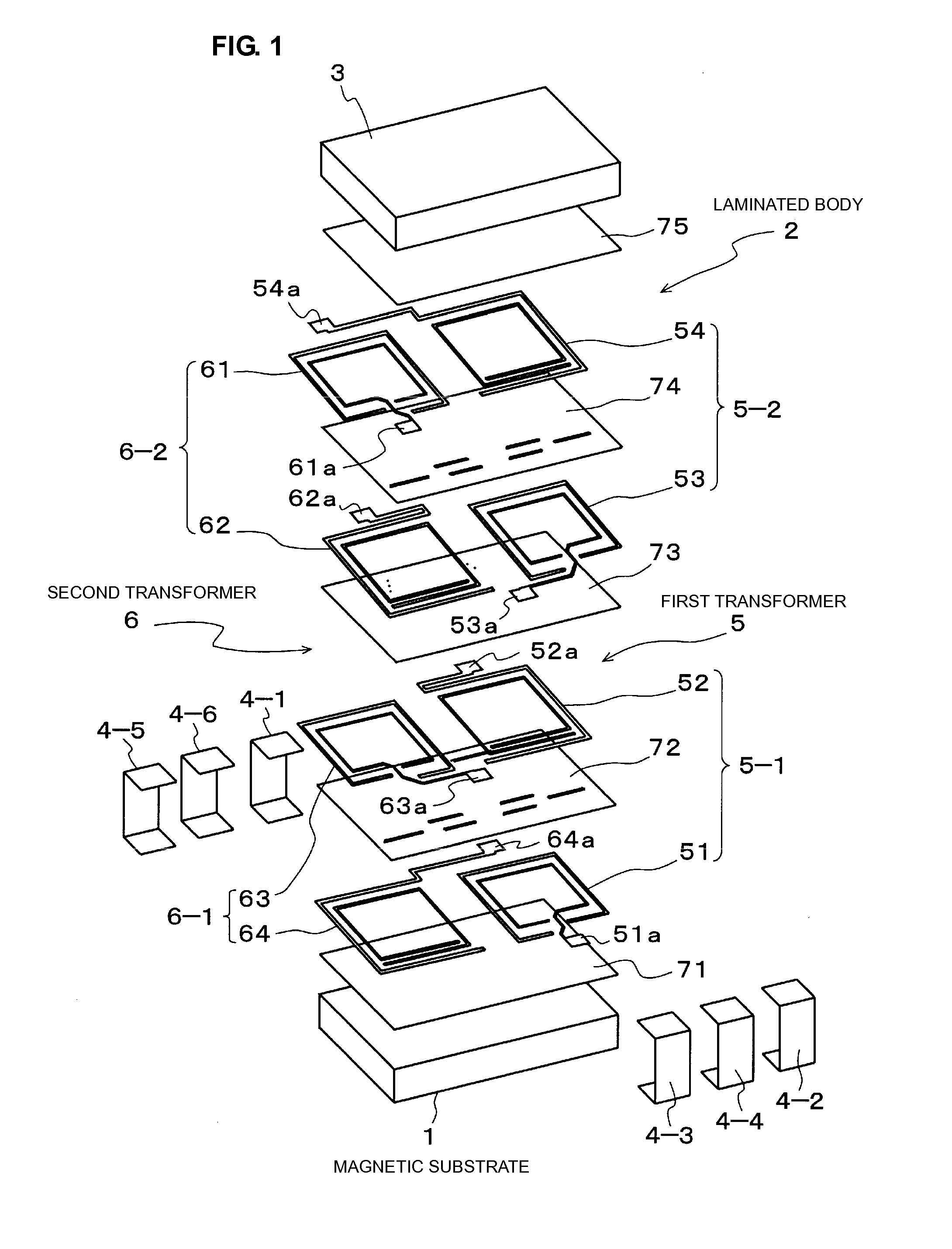
[0035]FIG. 1 is an exploded perspective view of a laminated balun transformer according to a first preferred embodiment of the present invention. FIG. 2 is an external view of the laminated balun transformer.
[0036]As shown in FIG. 2, in this preferred embodiment, a laminated balun transformer includes a magnetic substrate 1 which defines a first magnetic substrate, a laminated body 2 laminated on the magnetic substrate 1, a magnetic substrate 3 which defines a second magnetic substrate that is disposed on the laminated body 2, and external electrodes 4-1 to 4-6.
[0037]As shown in FIG. 1, the laminated body 2 includes a first transformer 5, a second transformer 6 that has substantially similar structure to the first transformer 5 and that is arranged in substantially the same direction as the first transformer 5, and an insulator 7 (see FIG. 2) that covers the first and second transformers 5 and 6.
[0038]The insulator 7 is, for example, a dielectric substance, and is formed by laminati...
second preferred embodiment
[0050]Next, a second preferred embodiment of the present invention will be described. FIG. 13 is an exploded perspective view of a laminated balun transformer according to a second preferred embodiment of the present invention. FIG. 14 is a plan view that shows a lower-layer conductive pattern of a primary coil 8-1. FIG. 15 is a plan view that shows an intermediate insulating layer 72. FIG. 16 is a plan view that shows an upper-layer conductive pattern of the primary coil 8-1. FIG. 17 is a plan view that shows a lower-layer conductive pattern of a secondary coil 8-2. FIG. 18 is a plan view that shows an intermediate insulating layer 74. FIG. 19 is a plan view that shows an upper-layer conductive pattern of the secondary coil 8-2.
[0051]As shown in FIG. 13, the laminated balun transformer according to this preferred embodiment is configured such that a laminated body 2 that includes a transformer 8 is disposed between magnetic substrates 1 and 3, and four terminal electrodes 4-1 to 4-...
third preferred embodiment
[0058]Next, a third preferred embodiment of the present invention will be described. FIG. 21 is an equivalent circuit diagram of a laminated balun transformer according to a third preferred embodiment of the present invention. In this preferred embodiment, as in the case of the laminated balun transformer shown in FIG. 1, in the structure in which a laminated body 2 is disposed between magnetic substrates 1 and 3, and external electrodes 4-1 to 4-6 are provided on the side surfaces, as shown in FIG. 21, n (where n is integer greater than or equal to 3) numbers of first transformer 9(1) to nth transformer 9(n) are incorporated in the laminated body 2.
[0059]Specifically, the left end of a primary coil 9-1 of the first transformer 9(1) is connected to the external electrode 4-1 to define an unbalanced terminal, and the right end thereof is connected to the external electrode 4-2 to define a first balanced terminal. In addition, in the last nth transformer 9(n), the left end of a second...
PUM
 Abstract
Description
Claims
Application Information