Magnet system and MRI apparatus

a magnet system and magnetic resonance imaging technology, applied in the field of magnet system and magnetic resonance imaging apparatus, can solve the problems of poor use efficiency of magnetic energy, high-efficiency magnets are expensive, and the pole pieces interfere with the magnetic field of permanent magnets, so as to improve the use efficiency of magnet energy, and improve the effect of magnetization in the different direction

Inactive Publication Date: 2009-03-19
GE MEDICAL SYST GLOBAL TECH CO LLC
View PDF15 Cites 22 Cited by
  • Summary
  • Abstract
  • Description
  • Claims
  • Application Information

AI Technical Summary

Benefits of technology

The technical effects of this patent involve improving the performance of MRIs (Magnetic Resonance Imaging) machines by utilizing better design features for the magnet system used during imaging. Specifically, the invention focuses on adding specific regions of magnetization that enhance the machine's ability to collect data while reducing energy waste. These improvements lead to more efficient use of the magnet energy, resulting in higher quality images without compromising patient safety.

Problems solved by technology

This patent discusses a problem related to the design of a magnet system used in an MRI machine. The current design causes poor utilization of magnetic energy due to the presence of leakage magnetic lines of force. To address this issue, the technical problem presented is how to improve the use efficiency of magnetic energy within the magnet system while maintaining its effectiveness at reducing eddy currents and improving image quality.

Method used


Image

  • Magnet system and MRI apparatus
  • Magnet system and MRI apparatus
  • Magnet system and MRI apparatus

Examples


Embodiment Construction

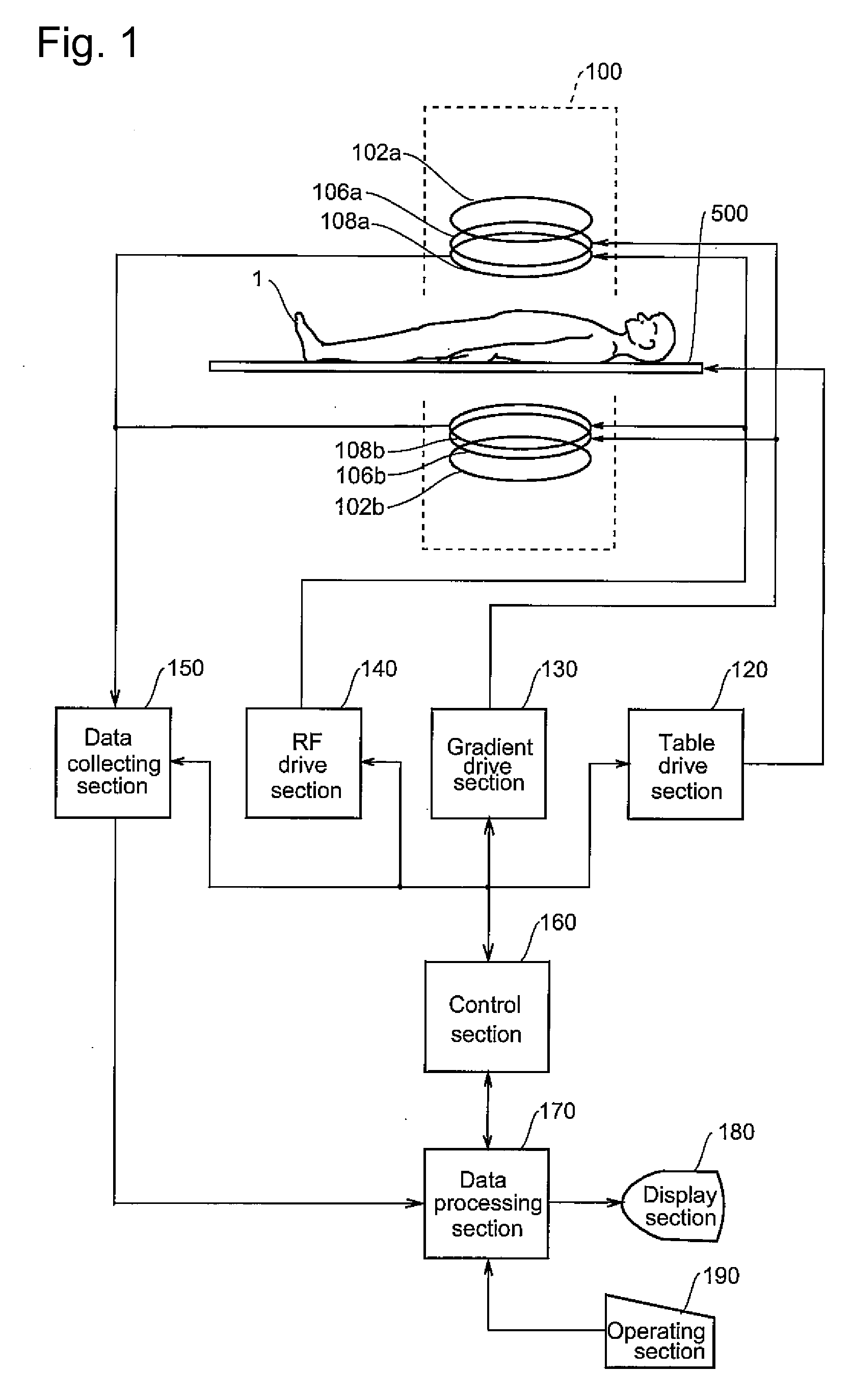
[0059]The best mode for carrying out the invention will be described in detail below with reference to drawings. Also, the invention is not limited to the mode for carrying out the invention. FIG. 1 is a block diagram of an MRI apparatus. This apparatus is an example of the best mode of implementing the invention. The configuration of this apparatus represents an apparatus, which is an example of the best mode of implementing the invention.

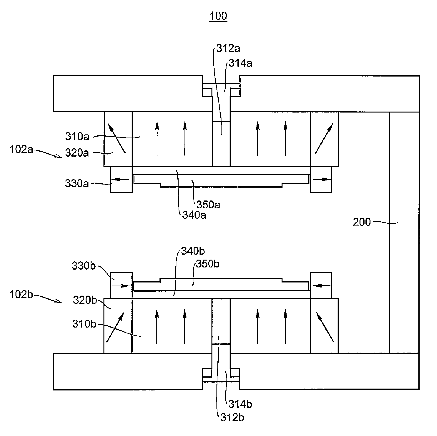
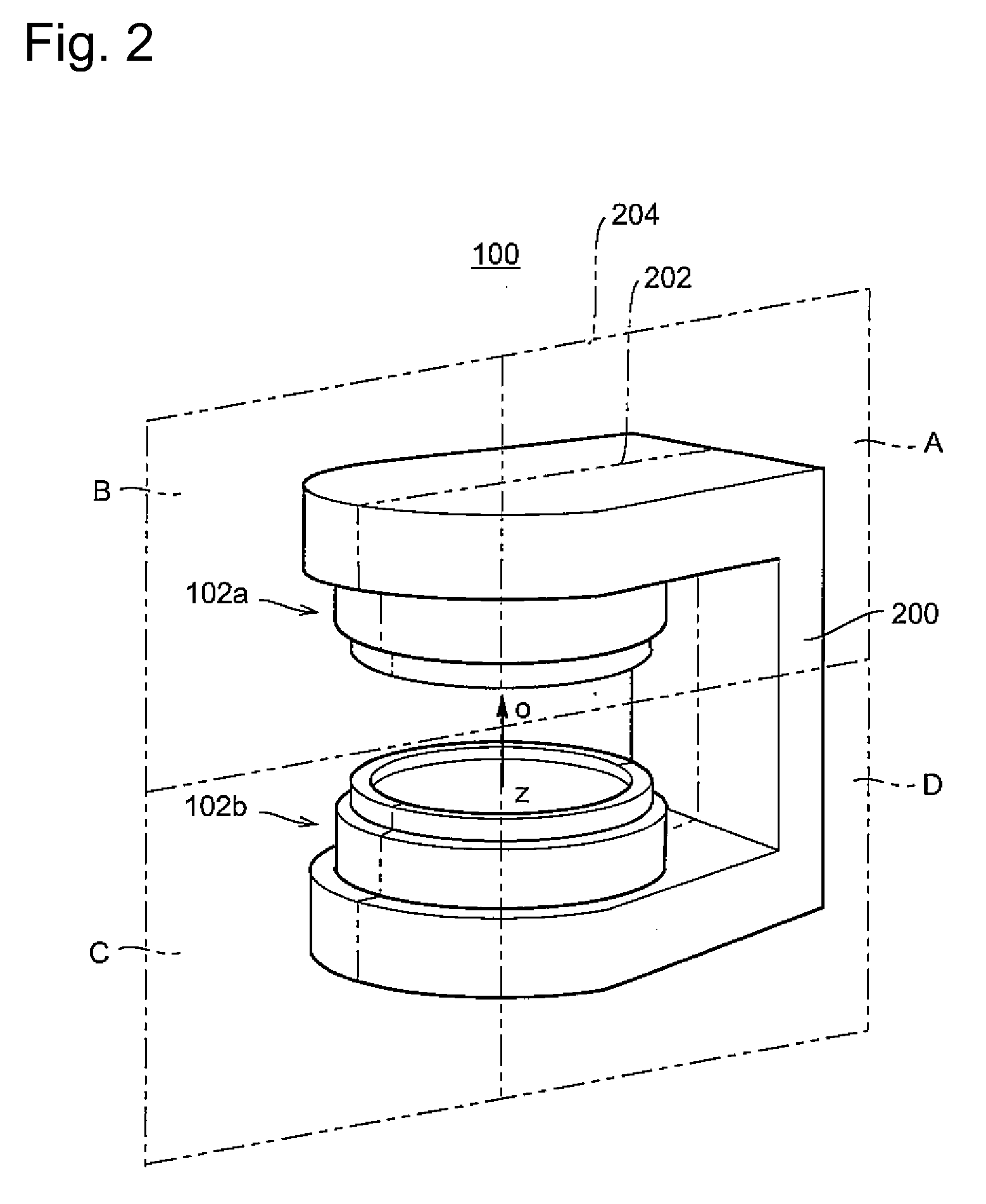
[0060]As shown in FIG. 1, the apparatus has a magnet system 100. The magnet system 100 has main magnetic field sections 102a and 102b, gradient coil sections 106a and 106b, and RF coil sections 108a and 108b.

[0061]The main magnetic field sections 102a and 102b, the gradient coil sections 106a and 106b, and the RF coil sections 108a and 108b are all paired ones, one opposite the other with a space between them. Also, they are substantially in the disc-like shapes and disposed coaxially.

[0062]A subject 1, mounted on a table 500, is brought into and...


PUM


Abstract

A magnet system having a pair of parallel plate-like permanent magnets in which magnetic poles of reversed polarities are opposed to each other with a space therebetween. The pair of permanent magnets includes main portions magnetized in the same direction as their thickness direction, and peripheral portions magnetized in a direction different from their thickness direction.

Description


Claims


Application Information

Patent Timeline
Owner GE MEDICAL SYST GLOBAL TECH CO LLC
Why Eureka
Try Eureka