Image display device, moire preventing film, optical filter, plasma display filter, and image display panel

a moire-preventing film and image display technology, applied in the direction of electrical equipment, instruments, electrical discharge tubes, etc., can solve the problems of limited moire reduction, health disorder of equipment operators, and often generated moire, so as to prevent film from being used, the effect of preventing image quality deterioration

Inactive Publication Date: 2009-03-19
FUJIFILM CORP
View PDF1 Cites 31 Cited by
  • Summary
  • Abstract
  • Description
  • Claims
  • Application Information

AI Technical Summary

Benefits of technology

[0011]In view of the above problems, an object of the present invention is to provide an image display device, an optical filter, a plasma d...

Problems solved by technology

It has been indicated that the EMI causes malfunction or failure of the electronic or electric equipment, and further causes health disorder of an operator of the equipment.
However, a moire is ofte...

Method used


Image

  • Image display device, moire preventing film, optical filter, plasma display filter, and image display panel
  • Image display device, moire preventing film, optical filter, plasma display filter, and image display panel
  • Image display device, moire preventing film, optical filter, plasma display filter, and image display panel

Examples


examples 1 to 15

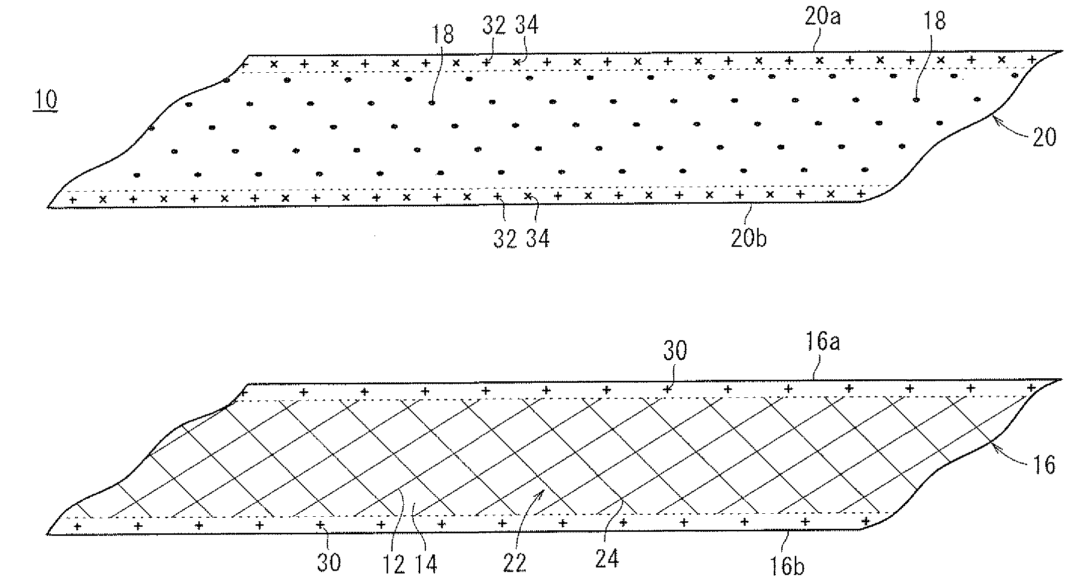
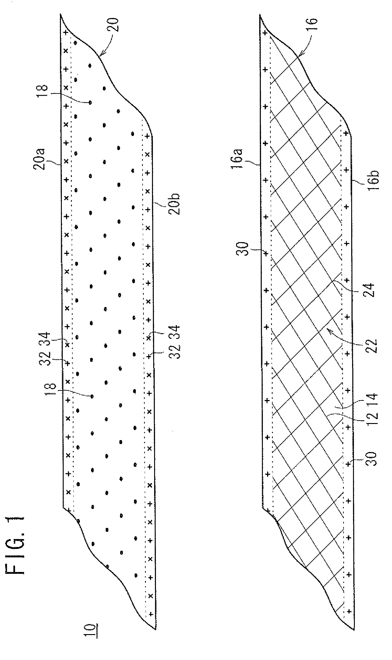
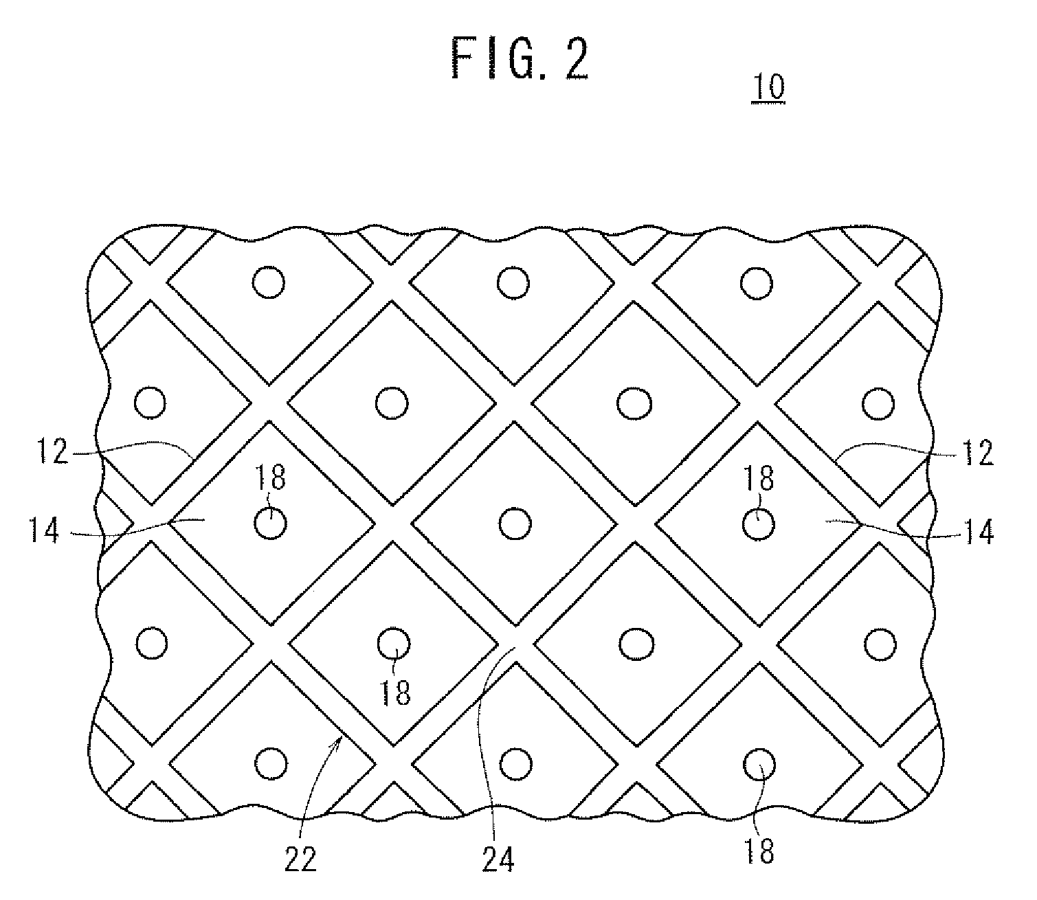
[0308]As shown in Table 1, in Examples 1 to 5, wire widths of the conductive portion 12 in the mesh pattern 22 were 14 μm, and the ratios (Sb / Sa) of the area Sb of the moire preventing part 18 to the area Sa of the intersection 24 were 0.5, 0.8, 1.0, 1.2, and 1.5, respectively. The moire preventing part 18 was positioned at the center of the opening portion 14 of the electromagnetic shielding film 16 in Examples 1 to 5, as well as in Examples 6 to 15.

[0309]In Examples 6 to 10, the wire widths were 20 μm, and the area ratios (Sb / Sa) were 0.5, 0.8, 1.0, 1.2, and 1.5, respectively.

[0310]In Examples 11 to 15, the wire widths were 30 μm, and the area ratios (Sb / Sa) were 0.5, 0.8, 1.0, 1.2, and 1.5, respectively.

[Evaluation]

(Evaluation of Conductivity)

[0311]The surface resistivity of each electromagnetic shielding film 16 was measured by LORESTA GP (Model No. MCP-T610) manufactured by Dia Instruments Co., Ltd. utilizing an in-line four-probe method (ASP), to evaluate the conductivity.

(Eva...


PUM


Abstract

An image display device comprises an electromagnetic shielding film and a moire preventing film attached thereto. The electromagnetic shielding film has a conductive portion and an opening portion, and the moire preventing film has a moire preventing part. When the conductive portion and the opening portion form a mesh pattern, the moire preventing part may be formed approximately at the center of the opening portion, and may be formed on an intersection of the mesh pattern.

Description

BACKGROUND OF THE INVENTION[0001]1. Field of the Invention[0002]The present invention relates to an image display device, a moire preventing film, an optical filter, a plasma display filter, and an image display panel, particularly to an image display device having an electromagnetic shielding film and a moire preventing film attached thereto, such as CRTs (cathode ray tubes), PDPs (plasma display panels), liquid crystal displays, EL (electroluminescence) displays, and FEDs (field emission displays). The electromagnetic shielding film is light transmittable and can shield an electromagnetic wave, and the moire preventing film can reduce moire generation by interference between the electromagnetic shielding film and pixels.[0003]2. Description of the Related Art[0004]Problems of electromagnetic interference (EMI) have been rapidly increasing in recent years along with increase in use of various electric and applied-electronic equipments. It has been indicated that the EMI causes malf...

Claims


Application Information

Patent Timeline
IPC IPC(8): G09G3/12
CPCH05K9/0096G02B2207/121G02F2001/133334H01J2329/89H01J29/89H01J2211/446H01J2329/869H01J5/16G02F1/133334
Inventor SANETO, RYUJISEKIGUCHI, MEGUMI
Owner FUJIFILM CORP
Why Eureka
Try Eureka