Encoding device, encoding method, encoding program, decoding device, decoding method, and decoding program

a technology of encoding device and encoding program, which is applied in the direction of signal generator with optical-mechanical scanning, color television with bandwidth reduction, etc., can solve the problem of increasing the workload involved in the process, and achieve the effect of increasing the subjective image quality of the decoded imag

Inactive Publication Date: 2009-03-19
SONY CORP
View PDF13 Cites 75 Cited by
  • Summary
  • Abstract
  • Description
  • Claims
  • Application Information

AI Technical Summary

Benefits of technology

[0017]In accordance with the present invention, the data based on the image data is segmented into the bit planes, and the data of the bit planes is successively output from the bit plane at the uppermost bit position to the bit plane at the predetermined position in the direction from the bit plane at the upper bit p

Problems solved by technology

The technique requires that two identical encoding processes be perfor

Method used


Image

  • Encoding device, encoding method, encoding program, decoding device, decoding method, and decoding program
  • Encoding device, encoding method, encoding program, decoding device, decoding method, and decoding program
  • Encoding device, encoding method, encoding program, decoding device, decoding method, and decoding program

Examples


Embodiment Construction

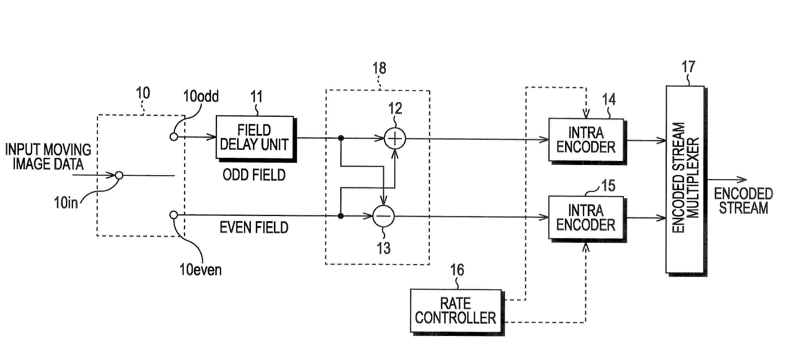
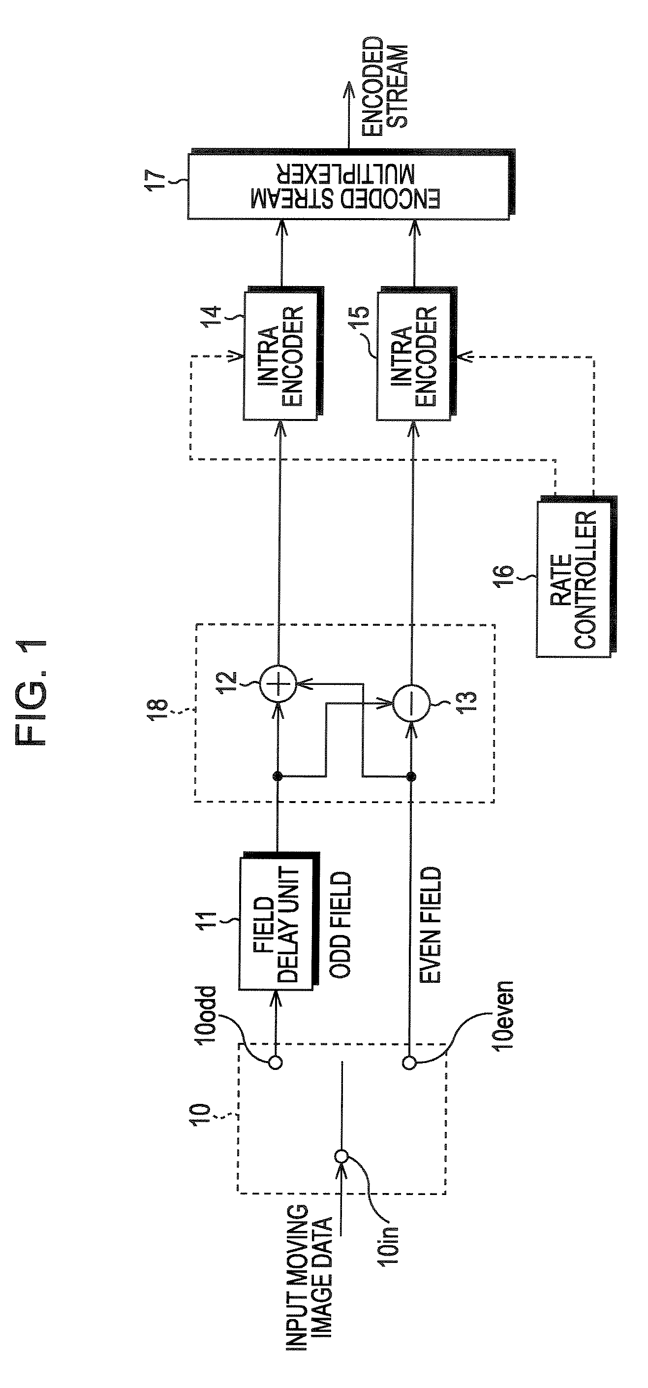
[0111]FIG. 1 illustrates the structure of an image encoding apparatus in accordance with one embodiment of the present invention. As shown in FIG. 1, the image encoding apparatus includes a switch 10, a field delay unit 11, an adder 12, a subtractor 13, an intra encoder 14, an intra encoder 15, a rate controller 16, and an encoded stream multiplexer 17. Hereinafter, the adder 12 and the subtractor 13 are also collectively referred to as an addition and subtraction unit 18.

[0112]Moving image data in interlace scanning is input to terminal 10 in of the switch 10. The switch 10 alternately switches between a selection output terminal 10odd and a selection output terminal 10even at field timing of the input image data.

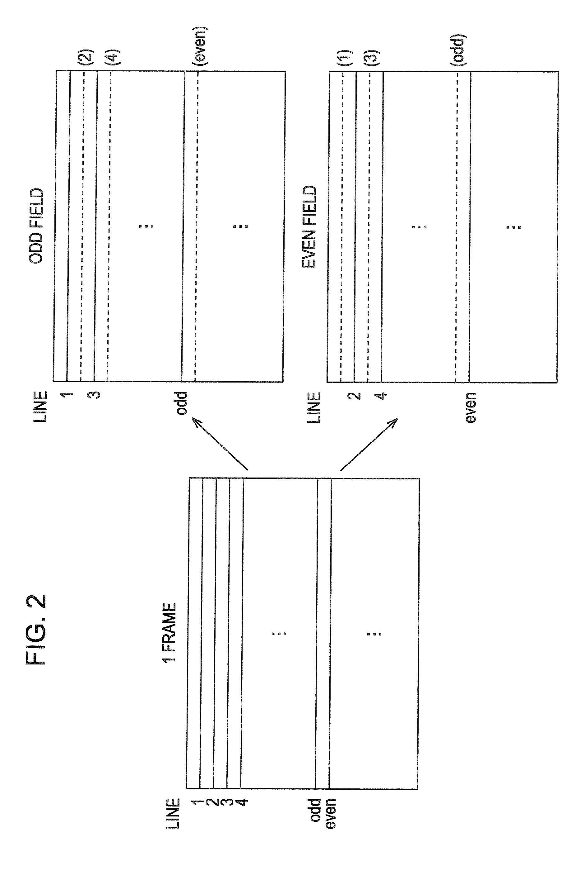
[0113]The moving image data in interlace scanning is briefly described here. As diagrammatically shown in FIG. 2, in interlace scanning, two images that are produced by decimating one line every two lines are alternated within one frame period to produce a moving image. Mo...


PUM


Abstract

The present invention relates to an encoding apparatus, an encoding method, an encoding program, a decoding apparatus, a decoding method and a decoding program for adaptively controlling an encoding bit rate. Coefficient data obtained using wavelet transform is quantized, and segmented into bit planes. The coefficient data is entropy encoded from the bit plane of the MSB in a direction from an upper bit position to a lower bit position. Entropy encoding is stopped at a bit position where an amount of code has reached a target amount. On the bit plane, the coefficient data is entropy encoded from a lower frequency region to a higher frequency region. Data greatly affecting subjective image quality of a decoded image is selectively output while the amount of code is easily controlled.

Description

TECHNICAL FIELD[0001]The present invention relates to an encoding apparatus, an encoding method, an encoding program, a decoding apparatus, a decoding method, and a decoding program for adaptively controlling an encoding bit rate.BACKGROUND ART[0002]Image data, such as digital video data, because of the large data size thereof, is typically compression encoded in a predetermined method and transmitted and / or recorded on a recording medium. Currently, MPEG 2 (Moving Picture Experts Group 2) is known as a standard method of compression encoding of digital video signal. In accordance with MPEG 2, compression encoding process is performed using DCT (Discrete Cosine Transform) and motion correction, and further variable length coding is used to increase data compression rate.[0003]In accordance with the encoding method for compression encoding data using variable length coding, like MPEG 2, the bit rate of the encoded data can become different from frame to frame. In the MPEG 2, an encod...

Claims


Application Information

Patent Timeline
IPC IPC(8): H04B1/66
CPCH04N19/63H04N19/184H04N19/152H04N19/91
Inventor FUKUHARA, TAKAHIROSUGIYAMA, AKIRAHOSAKA, KAZUHISA
Owner SONY CORP
Why Eureka
Try Eureka