Systems and methods for enhanced quantum key formation using an actively compensated QKD system

a quantum key and actively compensated technology, applied in the field of quantum cryptography, can solve problems such as reducing interference visibility, introducing errors that reveal her presence, and optical path length

Active Publication Date: 2009-03-19
MAGIQ TECH INC
View PDF13 Cites 46 Cited by
  • Summary
  • Abstract
  • Description
  • Claims
  • Application Information

AI Technical Summary

Benefits of technology

[0008]One aspect of the invention is a method of forming a quantum key by exchanging quantum signals between first and second QKD stations of an actively stabilized QKD system. The method includes using classical stabilization pulses to monitor the system visibility while quantum signals are being exchanged. The system visibility is the ability of the system to faithfully discriminate between two orthogonal quantum states. The method also includes generating an error signal SE proportional to the degree of system visibility reduction. The method further includes setting an error-signal threshold STH that defines an upper bound for the allowable system visibility reduction. The method also includes detecting the quantum signals to form qubits based on the quantum signals, and forming a raw quantum key by storing only below-threshold qubits—that is, qubits for which SE≦STH.

Problems solved by technology

As a consequence, an eavesdropper (“Eve”) that attempts to intercept or otherwise measure the exchanged qubits will introduce errors that reveal her presence.
A difference in the optical path length, known as “phase error,” reduces the interference visibility (“system visibility”) of the single-photon-level optical pulses (“quantum pulses”), which is detrimental to the efficiency of the QKD process.
When faced with high-frequency or high-amplitude disturbances, the feedback system's tracking range and bandwidth limitations may allow the shared interferometer to momentarily (e.g. over multiple qubit intervals) fall out of balance.
In some cases these limitations are manifested by operating near the limits of the actuator range.
However, depending on the implementation of this process and / or the speed of the actuator, resetting may cause a sudden spike (“glitch”) in phase error as the actuator hops across several modes and re-stabilizes itself at a mode near the midpoint of its operating range.
These phase errors in turn are projected onto the quantum signal and thus leads to increased QBER.
Realistically, this may not always be possible because there are likely other design tradeoffs that prevent such ideal performance.
Among these are the insertion loss of these components, the permissible power level of the classical feedback signal, and cost restrictions.
In all of these cases the feedback system alone may not be capable of continuously eliminating the time-varying phase error.
This is significant because each erroneous quantum signal bit leads to the loss of multiple error-free bits that are consumed in the error correction and privacy amplification processes.

Method used


Image

  • Systems and methods for enhanced quantum key formation using an actively compensated QKD system
  • Systems and methods for enhanced quantum key formation using an actively compensated QKD system
  • Systems and methods for enhanced quantum key formation using an actively compensated QKD system

Examples


Embodiment Construction

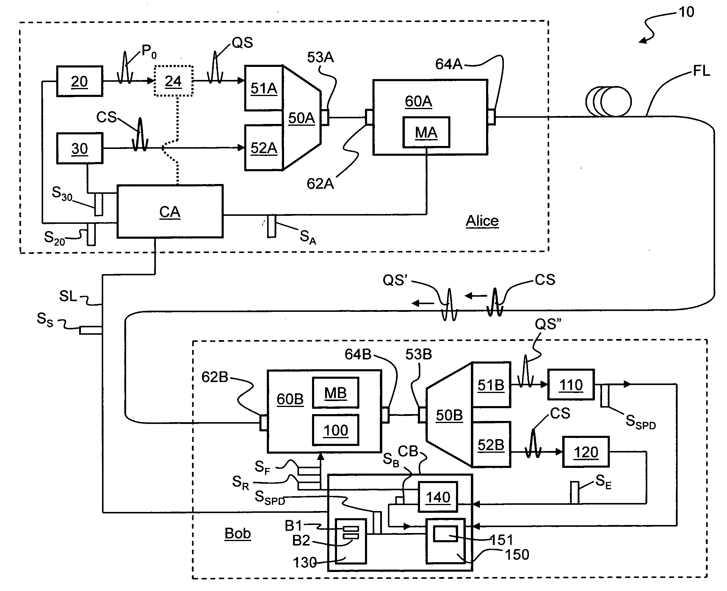
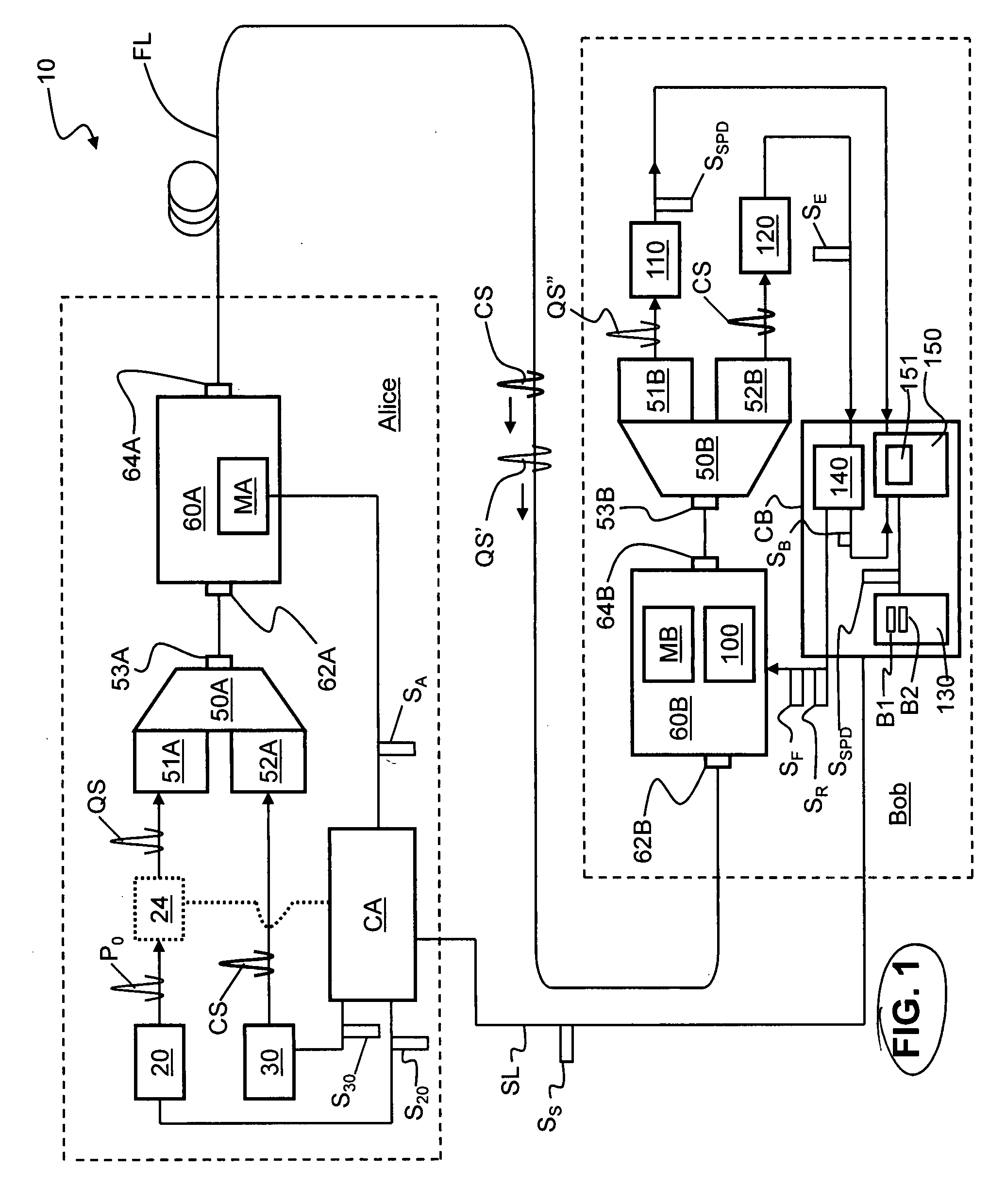
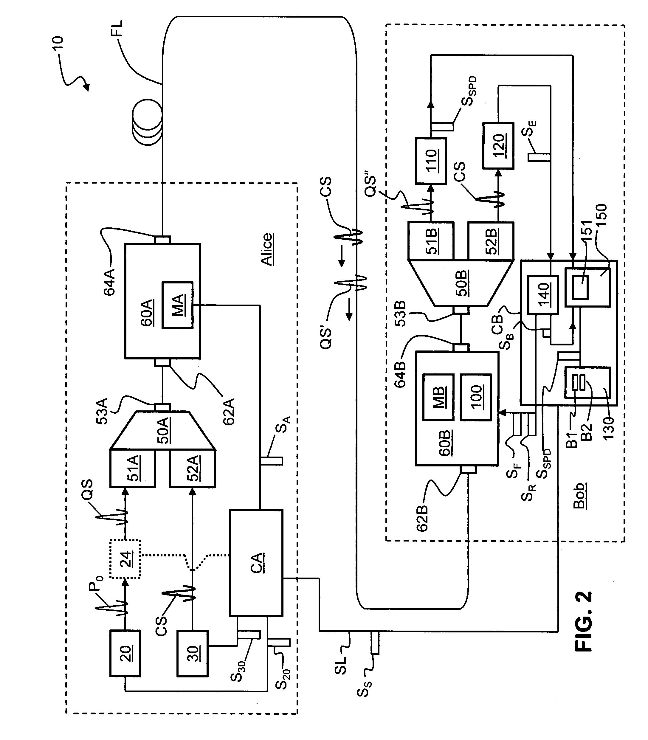
[0015]FIG. 1 is a schematic diagram of an actively stabilized QKD system 10 according to the present invention. QKD system 10 includes a QKD station Alice and a QKD station Bob that are optically coupled. In the example embodiment of FIG. 1, Alice and Bob are optically coupled by an optical fiber link FL. Alice and Bob communicate by encoded single-photon-level quantum signals QS. The encoding may be any type of encoding that changes the state of the photon. Usually, polarization encoding or phase encoding is used, as described in Bouwmeester. The present invention applies to any type of encoding scheme and QKD system that requires active stabilization in order to maintain the qubit error rate (QBER) at an acceptable level. In an example embodiment, such active stabilization utilizes classical optical signals CS that have the same or similar wavelength as the quantum signal QS. For example, in a polarization-based QKD system, a polarized classical signal is sent over the optical fib...


PUM


Abstract

Systems and methods for enhanced quantum key distribution (QKD) using an actively compensated QKD system. The method includes exchanging quantum signals between first and second QKD stations and measuring the quantum signal error. An error signal SE representative of the system visibility error is then generated. An error-signal threshold STH that defines a system visibility error limit is then selected. Those qubits measured with the condition SE>STH are called “above-threshold” qubits, while those qubits measured with the condition SE≦STH are called “below-threshold” qubits. Only below-threshold qubits are stored and used to form the final quantum key. This is accomplished by sending a blanking signal SB to the memory unit where the qubits are stored. The blanking signal prevents above-threshold qubits from being stored therein. The raw quantum key so formed has few errors and thus forms a longer final quantum key for a given number of exchanged quantum signals.

Description

FIELD OF THE INVENTION[0001]The present invention relates generally to quantum cryptography, and in particular to actively stabilized quantum key distribution (QKD) systems, and systems and methods for forming quantum keys using such systems.BACKGROUND ART[0002]QKD involves establishing a key between a sender (“Alice”) and a receiver (“Bob”) by using either single-photons or weak (e.g., 0.1 photon on average) optical signals (pulses) called “qubits” or “quantum signals” transmitted over a “quantum channel.” Unlike classical cryptography whose security depends on computational impracticality, the security of quantum cryptography is based on the quantum mechanical principle that any measurement of a quantum system in an unknown state will modify its state. As a consequence, an eavesdropper (“Eve”) that attempts to intercept or otherwise measure the exchanged qubits will introduce errors that reveal her presence.[0003]The general principles of quantum cryptography were first set forth ...

Claims


Application Information

Patent Timeline
Patent Type & Authority Applications(United States)
IPC IPC(8): H04L9/08
CPCH04L9/0858
Inventor BEAL, A. CRAIGLAGASSE, MICHAEL J.BERZANSKIS, AUDRIUS
Owner MAGIQ TECH INC
Why Eureka
Try Eureka