Eureka AIR delivers breakthrough ideas for toughest innovation challenges, trusted by R&D personnel around the world.

Transfer Device and Image Forming Apparatus Including the Same

Inactive Publication Date: 2009-03-19
SEIKO EPSON CORP
View PDF4 Cites 0 Cited by
  • Summary
  • Abstract
  • Description
  • Claims
  • Application Information

AI Technical Summary

Benefits of technology

[0007]It is an advantage of some aspects of the invention to provide a transfer device capable of increasing transfer efficiency and improving passing smoothness and separability of transfer material at a transfer nip, and an image forming apparatus including the transfer device.
[0008]A transfer device according to a first aspect of the invention includes: an image carrier belt having a base layer and an elastic layer; a first roller around which the image carrier belt is wound; a second roller around which the image carrier belt wound around the first roller and shifted; a third roller contacting the first roller via the image carrier belt; and a fourth roller contacting the second roller via the image carrier belt. A hardness H4 of the fourth roller and a hardness H6 of the image carrier belt on the second roller when the image carrier belt is wound around the second roller have the relationship of H6<H4. According to the structure which includes the image carrier belt having the elastic layer, transferability on a transfer material having large concaves and convexes improves, and thus clear images can be transferred on concaves. Moreover, the transfer material shifts while closely contacting the image carrier belt from the start position of the first transfer nip to the end position of the second transfer nip. Thus, preferable transfer can be performed. In addition, the transfer material is not greatly curved during shift, and the passing smoothness of the transfer material can be enhanced. In the condition H6<H4, a curved surface concaved on the second roller side is formed at the second transfer nip. Thus, separability of the transfer material is increased, and winding of the transfer material around the image carrier belt is prevented.
[0009]It is preferable that the relationship between the hardness H4 of the fourth roller, a hardness H1 of the second roller, and a hardness H5 of the elastic layer of the image carrier belt have the relationship of H4≧H1 and H1>H5. The elastic layer of the image carrier belt contributes to the formation of the curved surface at the second transfer nip concaved on the second roller side. As a result, separability of the transfer material is enhanced, and winding of the transfer material around the image carrier belt is prevented.

Problems solved by technology

However, the possible width of the transfer nip to be produced is limited due to the structure which winds the image carrier belt around the transfer roller.
Thus, improvement over the transfer efficiency is limited and difficult to be further raised.

Method used


Image

  • Transfer Device and Image Forming Apparatus Including the Same
  • Transfer Device and Image Forming Apparatus Including the Same
  • Transfer Device and Image Forming Apparatus Including the Same

Examples


first embodiment

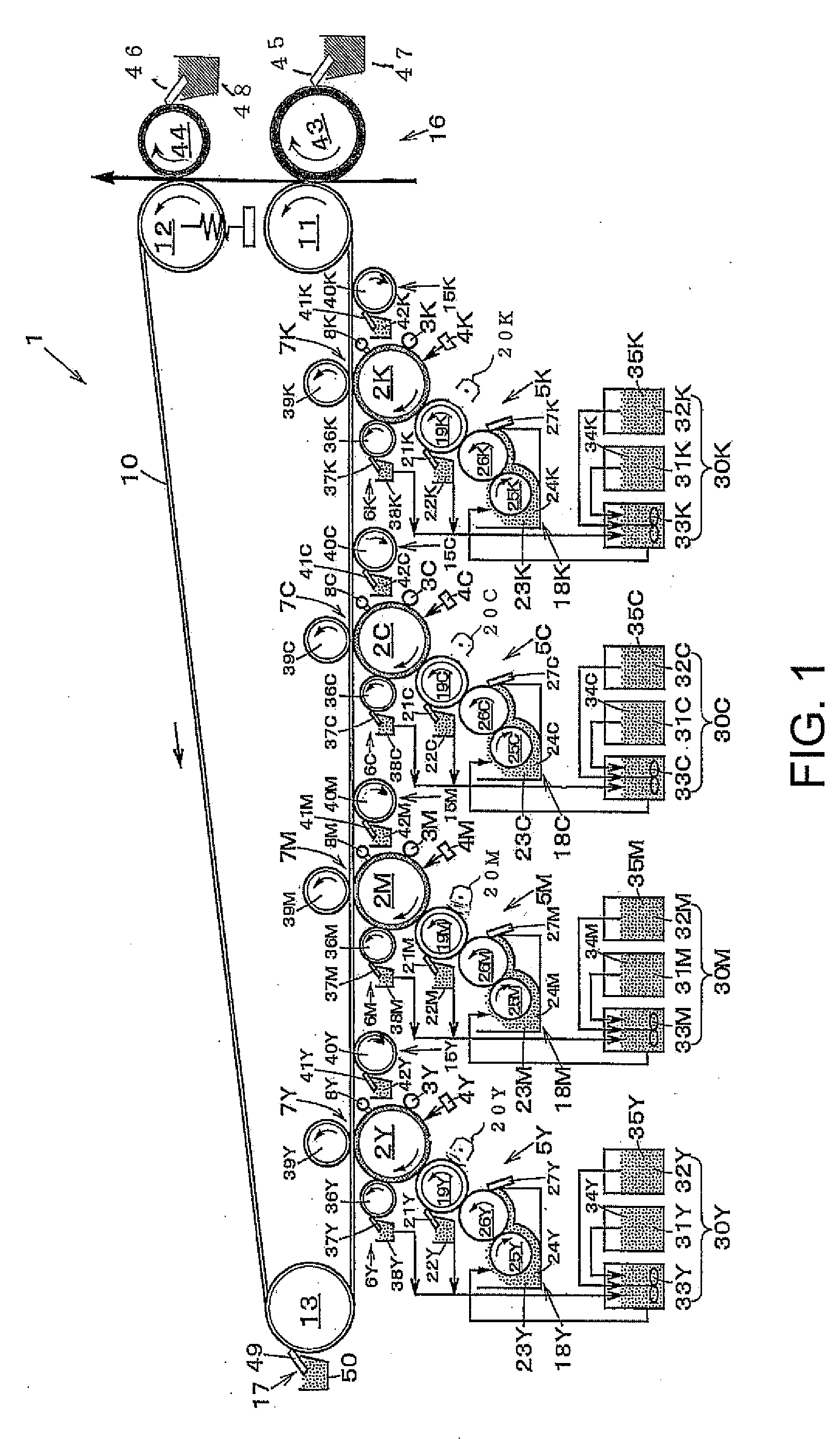
[0031]FIG. 1 illustrates an image forming apparatus according to the invention.

[0032]As illustrated in FIG. 1, an image forming apparatus 1 in the first embodiment includes photosensitive bodies 2Y, 2M, 2C, and 2K as latent image carriers for yellow (Y), magenta (M), cyan (C), and black (B) disposed in tandem. The photosensitive bodies 2Y, 2M, 2C, and 2K correspond to yellow sensitive body, magenta sensitive body, cyan sensitive body, and black sensitive body, respectively. Other components are similarly represented by adding the respective colors Y, M, C, and K to the symbols of the components. According to the example shown in FIG. 1, the respective photosensitive bodies 2Y, 2M, 2C, and 2K are constituted by photosensitive drums. The photosensitive bodies 2Y, 2M, 2C, and 2K may have endless shapes.

[0033]These photosensitive bodies 2Y, 2M, 2C, and 2K rotate clockwise in the directions indicated by arrows shown in FIG. 1 during operation. Electrifiers 3Y, 3M, 3C, and 3K, exposing un...

second embodiment

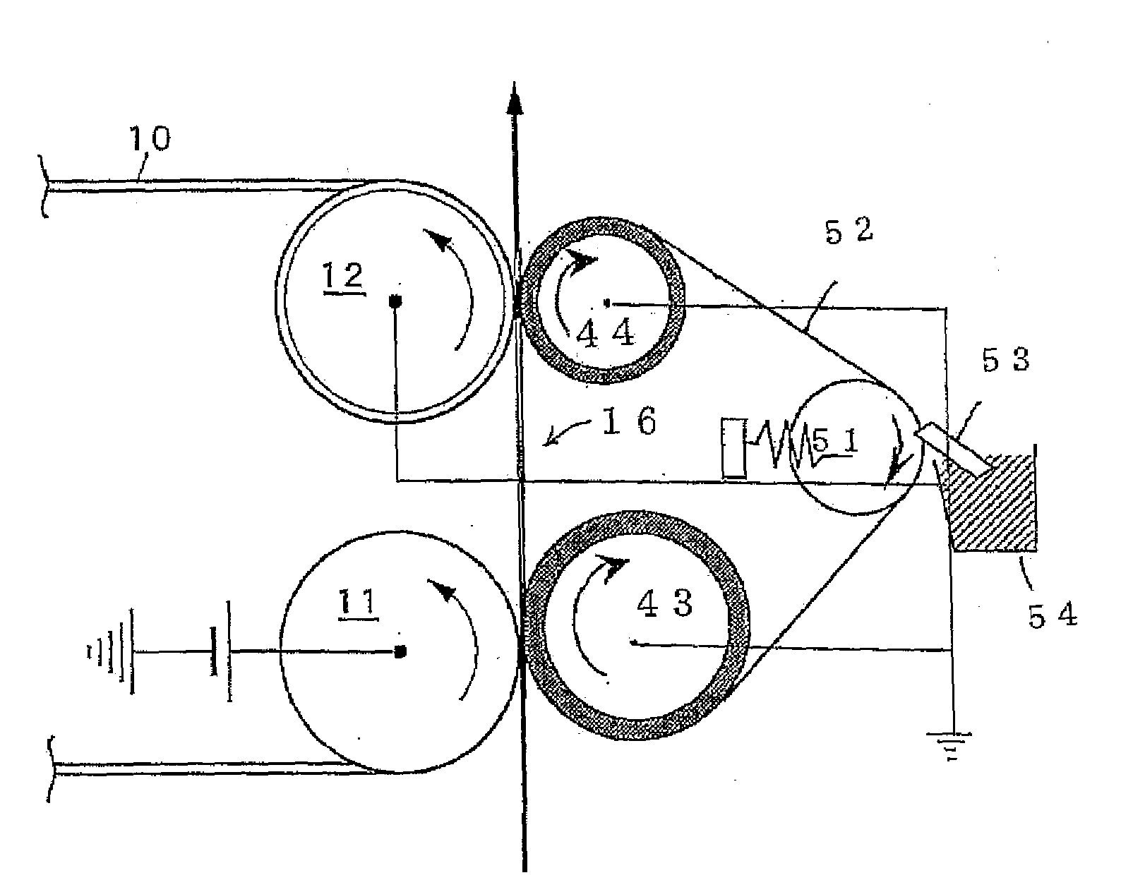
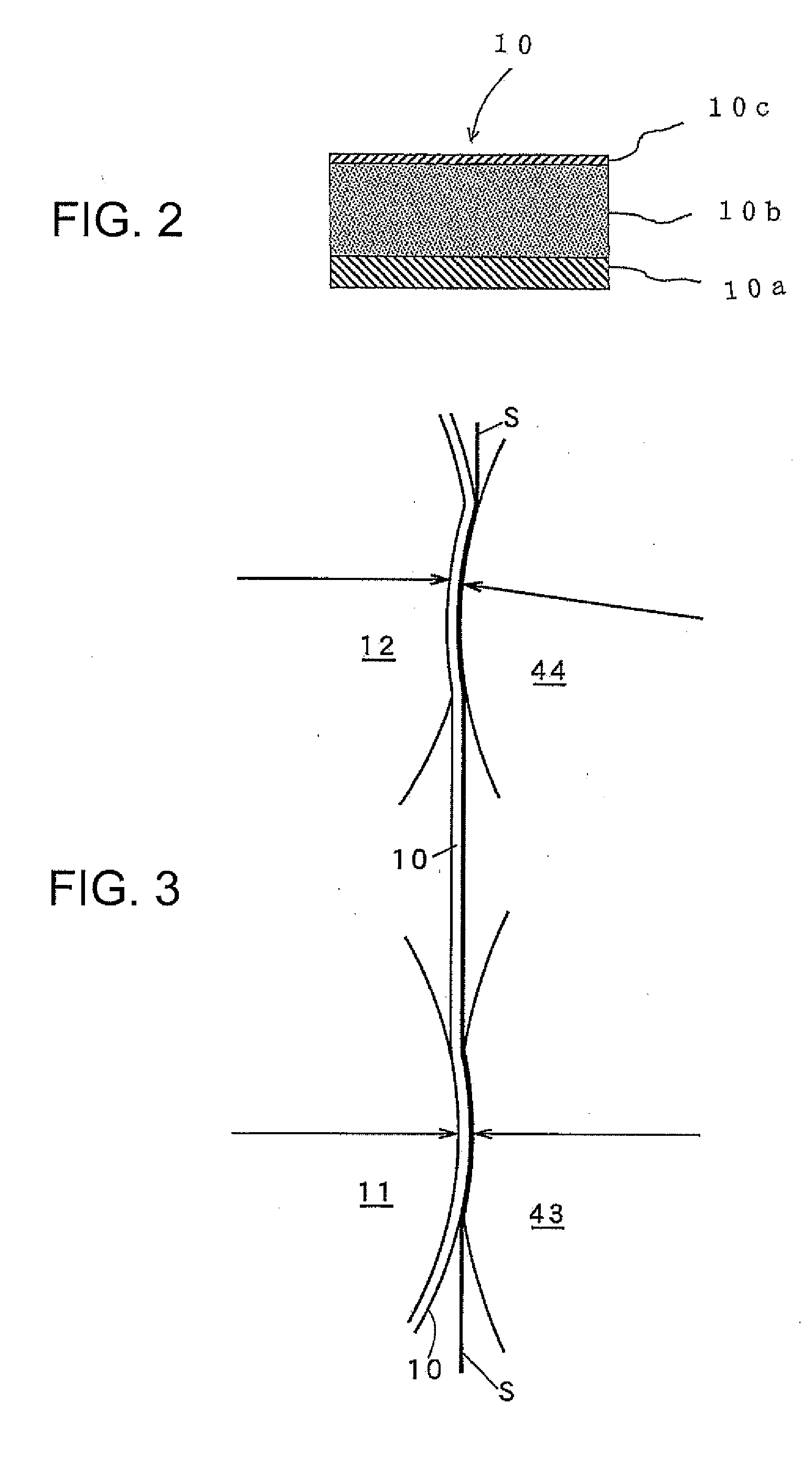
[0072]The secondary transfer device 16 included in the image forming apparatus in the second embodiment has a pair of secondary transfer rollers disposed with a predetermined clearance therebetween in the shift direction of the transfer material. The secondary transfer roller of the pair of the rollers disposed on the upstream side in the shift direction of the transfer material is the first secondary transfer roller 43. The secondary transfer roller of the pair of the rollers disposed on the downstream side in the shift direction of the transfer material is the second secondary transfer roller 44. An endless transfer material support belt 52 is wound around the first and second secondary transfer rollers 43 and 44, and tension is given to the transfer material support belt 52 by a tension roller 51. The first and second secondary transfer rollers 43 and 44 can contact the belt drive roller 11 and the following roller 12, respectively, via the intermediate transfer belt 10 and the t...


PUM


Abstract

A transfer device includes: an image carrier belt having a base layer and an elastic layer; a first roller around which the image carrier belt is wound; a second roller around which the image carrier belt wound around the first roller and shifted; a third roller contacting the first roller via the image carrier belt; and a fourth roller contacting the second roller via the image carrier belt. A hardness H4 of the fourth roller and a hardness H6 of the image carrier belt on the second roller when the image carrier belt is wound around the second roller have as the relationship of H6<H4.

Description

BACKGROUND[0001]1. Technical Field[0002]The present invention relates to a transfer device for transferring liquid developer image transferred on an image carrier belt onto a transfer material such as paper, and to an image forming apparatus including the transfer device.[0003]2. Related Art[0004]Currently, such a type of liquid developer image forming apparatus has been proposed which includes a transfer unit for transferring a liquid developer image transferred on an image carrier belt onto a transfer material such as paper (for example, see JP-A-2001-166611). According to the transfer device included in the image forming apparatus disclosed in JP-A-2001-166611, a transfer roller is pressed against the image carrier belt such that the image carrier belt can be wound around the transfer roller. As a result, a circular arc transfer nip having a nip shape and a predetermined width in the shift direction of the transfer material is produced to provide preferable transfer characteristi...

Claims


Application Information

Patent Timeline
IPC IPC(8): G03G15/16
CPCG03G15/1605G03G2215/1614G03G2215/0626G03G15/1685G03G15/162
Inventor KAMIJO, KOICHI
Owner SEIKO EPSON CORP
Why Eureka
Eureka Blog
Learn More