Eureka AIR delivers breakthrough ideas for toughest innovation challenges, trusted by R&D personnel around the world.

Automatic transmission fluid warmer coolant circulation system and design method thereof

Active Publication Date: 2016-09-22
HYUNDAI MOTOR CO LTD +1
View PDF13 Cites 0 Cited by
  • Summary
  • Abstract
  • Description
  • Claims
  • Application Information

AI Technical Summary

Benefits of technology

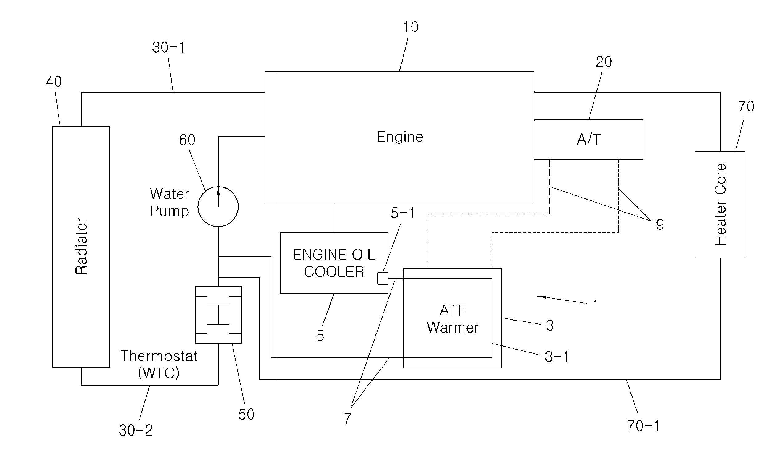
The present invention introduces an automatic transmission fluid (ATF) warmer coolant circulation system that improves fuel efficiency and transmission transfer efficiency by rapidly raising the temperature of the ATF. This is achieved by preheating the ATF while maintaining heating performance at a low temperature. This system reduces cost and weight through downsizing of the coolant line and valve elimination. The system consists of an engine oil cooler and an ATF warmer arranged in a serial manner, leading to improved fuel efficiency, reduced cost and weight, and improved heating performance at low temperatures.

Problems solved by technology

However, the conventional ATF warmer coolant circulation system applies the dualization of the ATF line and the engine coolant line, and the flow control valve type bypass vale in order to improve the fuel efficiency and maintain heating performance under the low temperature condition, such that it is bound to have system limitations which should make the engine coolant temperature of about 70° C. or more as the operation temperature even though the transmission transfer efficiency goes to the maximum at the ATF temperature of about 60° C. or more.
In particular, the bypass valve of the conventional ATF warmer coolant circulation system is installed at a front end of the ATF warmer, such that the heater core side flow rate is increased by the engine coolant not passing through the ATF warmer when the bypass valve is closed at 70° C. or less, whereas the ATF temperature rise is delayed when the bypass valve is opened at 70° C. or more due to the ATF preheating impossibility whereby it inevitably lacks the performance for the fuel efficiency improvement due to the low transmission transfer efficiency.

Method used


Image

  • Automatic transmission fluid warmer coolant circulation system and design method thereof
  • Automatic transmission fluid warmer coolant circulation system and design method thereof
  • Automatic transmission fluid warmer coolant circulation system and design method thereof

Examples


Embodiment Construction

[0037]Reference will now be made in detail to various embodiments of the present invention(s), examples of which are illustrated in the accompanying drawings and described below. While the invention(s) will be described in conjunction with exemplary embodiments, it will be understood that present description is not intended to limit the invention(s) to those exemplary embodiments. On the contrary, the invention(s) is / are intended to cover not only the exemplary embodiments, but also various alternatives, modifications, equivalents and other embodiments, which may be included within the spirit and scope of the invention as defined by the appended claims.

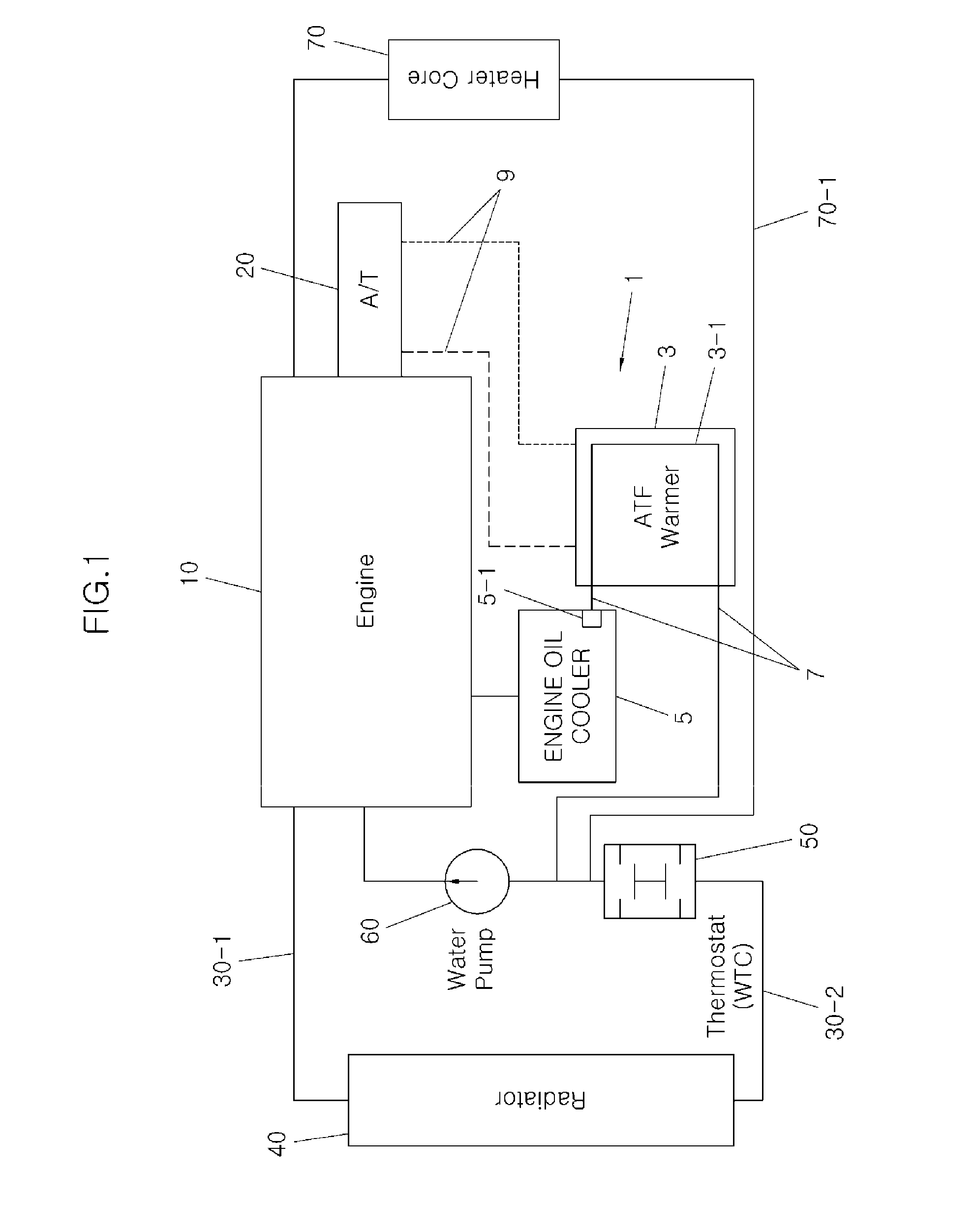
[0038]FIG. 1 is a diagram of an Automatic Transmission Fluid (ATF) warmer coolant circulation system according to the present invention.

[0039]As shown, an ATF warmer coolant circulation system 1 may be configured with an ATF warmer 3 connected with an engine oil cooler 5, an ATF coolant line 7 for introducing engine coolant, and an AT...


PUM


Abstract

An automatic transmission fluid (ATF) warmer coolant circulation system may include an ATF warmer connected to an engine oil cooler, in which engine coolant is circulated to the ATF warmer to preheat automatic transmission fluid of a transmission below an operation temperature of the ATF warmer.

Description

CROSS-REFERENCE TO RELATED APPLICATION[0001]The present application claims priority to Korean Patent Application No. 10-2015-0038097, filed Mar. 19, 2015, the entire contents of which is incorporated herein for all purposes by this reference.BACKGROUND OF THE INVENTION[0002]1. Field of the Invention[0003]The present invention relates to an automatic transmission fluid warmer coolant circulation system and design method thereof, and more particularly, to an automatic transmission fluid warmer coolant circulation system and design method thereof capable of preheating Automatic Transmission Fluid (ATF) in the low temperature condition of 70 degrees or less of the engine coolant.[0004]2. Description of Related Art[0005]In recent years, due to global high oil prices and CO2 regulation, as fuel efficiency improvement and eco-friendly property have been treated as key items in the vehicle development, automobile manufacturers have devoted all its efforts on a variety of technical developme...

Claims


Application Information

Patent Timeline
IPC IPC(8): F16H57/04
CPCF16H57/0475F16H2057/0087F16H57/0413F01P3/00F16H61/4165F16H2700/00F01P2003/006F01P3/12F01P7/14F16H41/30F16H61/4043
Inventor JEONG, CHI-WEONBAE, HYO-CHANYANG, YOUNG-BAECHOI, YOUNG-JINYUN, JOONG-SUJANG, KI-LYONGMOK, SEUNG-HOAHN, KWANG-WEON
Owner HYUNDAI MOTOR CO LTD
Why Eureka
Eureka Blog
Learn More